Form No. 3357-123 Rev B Dingo® TX 420 and TX 425 Compact Utility Loader Model No. 22306—Serial No. 270000001 and Up Model No. 22306G—Serial No. 270000001 and Up Model No. 22307—Serial No. 270000001 and Up Register at www.Toro.com.
Warning Model No. CALIFORNIA Proposition 65 Warning The engine exhaust from this product contains chemicals known to the State of California to cause cancer, birth defects, or other reproductive harm. Serial No. This manual identifies potential hazards and has safety messages identified by the safety alert symbol (Figure 1), which signals a hazard that may cause serious injury or death if you do not follow the recommended precautions.
Contents Adjusting the Traction Control Alignment ...................................................... 37 Adjusting the Traction Control Neutral Position.......................................................... 37 Adjusting the Tracking of the Traction Control, Full Forward Position........................ 38 Hydraulic System Maintenance ............................... 39 Replacing the Hydraulic Filter ............................. 39 Changing the Hydraulic Fluid .............................
Safety • Inspect the area where the equipment is to be used and remove all objects such as rocks, toys, and wire which can be thrown by the machine. • Use extra care when handling gasoline and other fuels. They are flammable and vapors are explosive. – Use only an approved container – Never remove the gas cap or add fuel with the engine running. Allow the engine to cool before refueling. Do not smoke. – Never refuel or drain the machine indoors.
• Read all attachment manuals. • Ensure that the area is clear of other people before operating the traction unit. Stop the traction unit if anyone enters the area. • Never leave a running traction unit unattended. Always lower the loader arms, stop the engine, set the parking brake, and remove the key before leaving. • Do not exceed the rated operating capacity, as the traction unit may become unstable which may result in loss of control. • Do not carry a load with the arms raised.
– Keep container nozzle in contact with the tank during filling. • Let the engine cool before storing and do not store near flame. • Do not store fuel near flames or drain indoors. • Park the machine on level ground. Never allow untrained personnel to service the machine. • Use jack stands to support components when required. • Carefully release pressure from components with stored energy. • Disconnect the battery or remove the spark plug wires before making any repairs.
Slope Chart 7
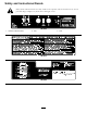
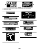
Safety and Instructional Decals Safety decals and instructions are easily visible to the operator and are located near any area of potential danger. Replace any decal that is damaged or lost. 108-4658 1. Operator’s Manual location. 2. Fast 3.
107-9309 1. Warning—read the Operator’s Manual for information on charging the battery; contains lead; do not discard. 2. Read the Operator’s Manual. NECTING COUPLERS. WHEN CONNECTING COUPLERS. E WEAR SHOULD BE WORNPROTECTIVE WEAR SHOULD BE WORN T. MAY BE HOT. C COUPLERS HYDRAULIC COUPLERS NECTING COUPLERS. WHEN CONNECTING COUPLERS. E WEAR SHOULD BE WORNPROTECTIVE WEAR SHOULD BE WORN T. MAY BE HOT.
8-4670 108-4671 93-9084 1. Lift point 2.
Setup 3. When the battery is fully charged, unplug the charger from the electrical outlet, then disconnect the charger leads from the battery posts (Figure 2). 1 4. Close the rear access cover. 2 Charging the Battery No Parts Required Checking Fluid Levels Procedure No Parts Required Warning Procedure CALIFORNIA Proposition 65 Warning Battery posts, terminals, and related accessories contain lead and lead compounds, chemicals known to the State of California to cause cancer and reproductive harm.
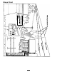
Product Overview Figure 3 1. 2. 3. 4. Track Track adjustment chamber Lift cylinder Cylinder lock 5. 6. 7. 8. Loader arms 9. Mount plate Hood 10. Tie-down/lift loop Auxiliary hydraulic couplers 11. Control panel Tilt cylinder 12. Rear access cover 13. Fuel tank 14. Reverse safety plate Controls To stop the engine, rotate the key to the off position. Become familiar with all the controls (Figure 4) before you start the engine and operate the traction unit.
The farther you move the traction control in any direction, the faster the traction unit will move in that direction. By moving the lever to an intermediate position (such as, forward and left), you can move the loader arms and tilt the attachment at the same time. To stop, release the traction control. Auxiliary Hydraulics Lever To operate a hydraulic attachment in the forward direction, rotate the auxiliary hydraulics lever rearward and pull it down to the reference bar (Figure 7, number 1).
Fuel Gauge This gauge measures the amount of fuel in the fuel tank. Hydraulic Oil Temperature Light (Dingo TX 425 only) If the hydraulic oil gets too hot, this light illuminates and an audible alarm sounds. If this happens, stop the engine and allow the traction unit to cool. Hour Meter/Tachometer When the engine is off, the hour meter/tachometer displays the number of hours of operation that have been logged on the traction unit.
Specifications Note: Specifications and design are subject to change without notice. TX 420, Model 22306 Width 34 inches (86 cm) Length 71 inches (180 cm) Height 46 inches (117 cm) Weight 1880 lb (853 Kg) Operating capacity 500 lb (227 Kg) Tipping capacity 1480 lb (671 Kg) Wheelbase 31.
Stability Data The following tables list the maximum slope recommended for the traction unit in the positions listed in the tables. Slopes over the listed degree may cause the traction unit to become unstable. The data in the tables assume that the loader arms are fully lowered; raised arms may affect the stability. In each attachment manual is a set of three stability ratings, one for each hill position.
Operation In certain conditions during fueling, static electricity can be released causing a spark which can ignite the gasoline vapors. A fire or explosion from gasoline can burn you and others and can damage property. Note: Determine the left and right sides of the machine from the normal operating position. Important: Before operating, check the fuel and oil level, and remove debris from the traction unit. Also, ensure that the area is clear of people and debris.
chance of varnish deposits in the fuel system, use fuel stabilizer at all times. Filling the Fuel Tank 1. Park the traction unit on a level surface, lower the loader arms, and stop the engine. 2. Remove the key and allow the engine to cool. 3. Clean around the fuel tank cap and remove it. 4. Add unleaded gasoline to the fuel tank, until the level is just below the bottom of the filler neck. Figure 10 1. Filler cap Important: This space in the tank allows gasoline to expand.
lower), hydraulic system damage could occur. When starting the engine in cold conditions, allow the engine to run in the middle throttle position for 2 to 5 minutes before moving the throttle to fast (rabbit). Note: If outdoor temperature is below freezing, store the traction unit in a garage to keep it warmer and aid in starting. Stopping the Engine 1. Move the throttle lever to the slow (turtle) position. Figure 11 1. Filler neck cap 2. Lower the loader arms to the ground. 2. Dipstick 3.
Figure 13 1. Cylinder lock 2. Lift cylinder 3. Clevis pin 4. Hairpin cotter Figure 12 1. Left tow valve (right track) 2. Right tow valve (left track) 4. Tow the traction unit as required. 5. Lower the cylinder lock over the cylinder rod and secure it with the clevis pin and hairpin cotter (Figure 13). 5. When the traction unit has been repaired, close the tow valves before operating it. 6. Slowly lower the loader arms until cylinder lock contacts the cylinder body and rod end.
Installing an Attachment Important: Use only Toro-approved attachments. Attachments can change the stability and the operating characteristics of the traction unit. The warranty of the traction unit may be voided if used with unapproved attachments. Important: Before installing the attachment, ensure that the mount plates are free of any dirt or debris and that the pins rotate freely. If the pins do not rotate freely, grease them. 1.
Important: Connect the attachment hoses together to prevent hydraulic system contamination during storage. 6. Push the attachment male connector into the female connector on the traction unit. Note: When you connect the attachment male connector first, you will relieve any pressure built up in the attachment. 6. Install the protective covers onto the hydraulic couplers on the traction unit. 7. Start the engine, tilt the mount plate forward, and back the traction unit away from the attachment.
Maintenance Note: Determine the left and right sides of the machine from the normal operating position. Recommended Maintenance Schedule(s) Maintenance Service Interval Maintenance Procedure After the first 8 hours • Replace the hydraulic filter. After the first 50 hours • Change the engine oil and filter. • Check and adjust the track tension. Before each use or daily • • • • • Check the engine oil level. Grease the traction unit. Check the condition of and clean the tracks.
If you leave the key in the ignition switch, someone could accidently start the engine and seriously injure you or other bystanders. Remove the key from the ignition and disconnect the wire from the spark plug before you do any maintenance. Set the wire aside so that it does not accidentally contact the spark plug. Premaintenance Procedures Before opening any of the covers, stop the engine and remove the key. Allow the engine to cool before opening any covers Opening the Hood 1.
Removing the Front Screen If the engine has been running the heat shield will be very hot and could burn you. Allow the traction unit cool completely before touching the heat shield. 1. Open the hood and remove both side screens. Figure 18 2. Loosen the bolts securing the front weight (Figure 20). 1. Hand knob 2. Tilt the rear access cover down and remove to access the internal components (Figure 18). Closing the Rear Access Cover 1.
Lubrication Greasing the Traction Unit Grease all pivot joints every 8 operating hours and immediately after every washing. Grease Type: General-purpose grease. 1. Lower the loader arms and stop the engine. Remove the key. 2. Clean the grease fittings with a rag. Figure 21 1. Front screen 3. Connect a grease gun to each fitting (Figure 23 and Figure 24). 2. Bolts (left side bolt not shown) 6. Remove the shoulder bolts and nuts securing the oil cooler to the top of the front screen (Figure 22).
Engine Maintenance Cleaning the Foam Pre-filter Important: Replace the foam element if it is torn or worn. Servicing the Air Cleaner Foam Pre-filter: Clean every 25 operating hours. 1. Wash the foam pre-filter in liquid soap and warm water. When clean, rinse it thoroughly. Paper Filter: Check for damage every 25 operating hours. Replace after every 100 operating hours. 2. Dry the pre-filter by squeezing it in a clean cloth (do not wring).
3. Install the cover, spacer and secure it with the cover nut (Figure 25). Torque the nut to 95 inch-lb (11 N-m). Components will be hot if the traction unit has been running. If you touch hot components you may be burned. 4. Install the air cleaner cover and secure with the knob (Figure 25). Allow the traction unit to cool before performing maintenance or touching components under the hood. 5. Close the hood. Servicing the Engine Oil 4. Remove the drain plug (Figure 29).
Figure 30 Figure 31 1. Oil filter 1. Spark plug wire 2. Spark plug 4. Pour new oil of the proper type through the center hole of the filter. Stop pouring when the oil reaches the bottom of the threads. 4. Clean around the spark plugs. 5. Remove both spark plugs and metal washers. 5. Allow a minute or two for the oil to be absorbed by filter material, then pour off the excess oil. Checking the Spark Plugs 1. Look at the center of both spark plugs (Figure 32).
Draining the Fuel Tank Fuel System Maintenance In certain conditions, gasoline is extremely flammable and highly explosive. A fire or explosion from gasoline can burn you and others and can damage property. Changing the Fuel Filter Change the fuel filter after every 200 operating hours or yearly, whichever occurs first. • Drain gasoline from the fuel tank when the engine is cold. Do this outdoors in an open area. Wipe up any gasoline that spills. 1.
Electrical System Maintenance 2 Servicing the Battery 3 Warning CALIFORNIA Proposition 65 Warning Battery posts, terminals, and related accessories contain lead and lead compounds, chemicals known to the State of California to cause cancer and reproductive harm. Wash hands after handling. 1 G003794 Figure 34 1. Filler caps 2. Upper line 3. Lower line 4. If the electrolyte is low, add the required amount of distilled water; refer to Adding Water to the Battery.
6. Install the battery filler caps. Drive System Maintenance Charging the Battery Servicing the Tracks level is up to the Upper line (Figure 34) on the battery case. Cleaning the Tracks Check the tracks for excessive wear and clean them periodically. If the tracks are worn, replace them. 1. With a bucket on the loader arms, lower the bucket to the ground so that the front of the traction unit lifts off of the ground a few inches. 2. Stop the engine, and remove the key. 3.
1. Lower the loader arms, stop the engine, and remove the key. 2. Lift/support the side of the unit to be worked on so that the track is 3 to 4 inches (7.6 to 10 cm) off of the ground. 3. Remove the locking bolt and nut (Figure 38). 4. Using a 1/2 inch drive socket, release the drive tension by turning the tensioning screw clockwise (Figure 38 and Figure 39). Figure 37 1. 2-3/4 inches (7 cm) 1. Lower the loader arms, stop the engine, and remove the key. 2.
11. Turn the tensioning screw counter-clockwise until the distance between the tension nut and the back of the fork tube (Figure 37) is 2-3/4 inches (7 cm). 6. Remove the nut securing the outer tension wheel and remove the wheel (Figure 40). 7. Remove the track (Figure 40). 12. Align the closest notch in the tension screw to the locking bolt hole and secure the screw with the locking bolt and nut. 8. Remove the nut securing the inner tension wheel and remove the wheel (Figure 40). 13.
Belt Maintenance Inspecting/Replacing the Drive Belt Inspect the drive belt, located behind the engine, every 25 operating hours. Replace the belt if you find any signs of wear, cracks, or damage or after 200 operating hours, whichever comes first. Figure 41 1. Road wheels To replace the drive belt, complete the following procedure: 3. Track guide bolts (only two shown) 2.
Figure 44 1. Idler pulley assembly 2. Drive belt routing 5. Remove the belt from the three pulleys (Figure 45). Figure 43 1. Spring removal tool 2. Drive belt 4. Idler pulley 5. Engine (see-through for illustrative purposes) Figure 45 3. Idler pulley spring 6. Install a new drive belt around the three pulleys (Figure 44). 4. Remove the idler pulley spring from the idler pulley assembly (Figure 44). 7. Install the end of the idler pulley spring to the arm on the idler pulley assembly. 8.
Controls System Maintenance The factory adjusts the controls before shipping the traction unit. However, after many hours of use, you may need to adjust the traction control alignment, the neutral position of the traction control, and the tracking of the traction control in the full forward position. Figure 47 Important: To adjust the controls properly, complete each procedure in the order listed. 1. Traction control 2. Stem , bolt and nut 5.
1. Drive the traction unit with the traction control against the reference bar, noting which direction the traction unit veers. 2. Release the traction control. 3. If the traction unit veers to the left, loosen the right jam nut and adjust the tracking set screw on the front of the traction control (Figure 50). 4. If the traction unit veers to the right, loosen the left jam nut and adjust the tracking set screw on the front of the traction control (Figure 50). Figure 49 1. Traction rod 2. Jam nut 4.
Hydraulic System Maintenance Hydraulic fluid escaping under pressure can penetrate skin and cause injury. Fluid injected into the skin must be surgically removed within a few hours by a doctor familiar with this form of injury or gangrene may result. Replacing the Hydraulic Filter Important: Do not substitute an automotive oil filter or severe hydraulic system damage may result. • Keep your body and hands away from pin hole leaks or nozzles that eject high pressure hydraulic fluid.
6. Place a large drain pain (capable of holding 15 US gallons) under the drain plug on the front of the traction unit (Figure 53). Hydraulic fluid escaping under pressure can penetrate skin and cause injury. Fluid injected into the skin must be surgically removed within a few hours by a doctor familiar with this form of injury or gangrene may result. Note: The drain plug is located behind the front weight, under the muffler.
Cleaning the Chassis Cleaning Over time, the chassis under the engine collects dirt and debris that must be removed. Using a flashlight, open the hood and inspect the area under the engine on a regular basis.
21. Replace the rear panel and secure it with the six bolts and nuts removed previously (Figure 54). 22. Secure the battery tray with the bolts and washers removed previously. 23. Install the side weights with the bolts, washers, and lock washers removed previously (Figure 54). 24. Close the rear access cover. 25. Lower the traction unit to the ground. Figure 55 1. Black wire 2. Orange wire 13. Carefully remove the tank and set it upright to keep from spilling the gasoline.
Storage D. Restart the engine and run it until it stops. E. Choke the engine. 1. Lower the loader arms, stop the engine, and remove the key. F. Start and run the engine until it will not start again. 2. Remove dirt and grime from the external parts of the entire traction unit, especially the engine. Clean dirt and chaff from the outside of the engine cylinder head fins and blower housing. G. Dispose of fuel properly. Recycle as per local codes.
Troubleshooting Problem The starter does not crank The engine will not start, starts hard, or fails to keep running. Possible Cause 1. The battery is discharged. 1. Charge the battery or replace it. 2. The electrical connections are corroded or loose. 3. The relay or switch is damaged. 2. Check the electrical connections for good contact. 3. Contact your Authorized Service Dealer. 1. The fuel tank is empty. 1. Fill the fuel tank with gasoline. 2. The choke is not on. 3. The air cleaner is dirty. 2.
Schematics Electrical Schematic (Rev.
Hydraulic Schematic (Rev.
Evaporative Emission Control Warranty Statement California Evaporative Emission Control Warranty Statement Your Warranty Rights and Obligations Introduction The California Air Resources Board and The Toro® Company are pleased to explain the evaporative emission control system’s warranty on your 2007 model year equipment. In California, new equipment that use small off-road engines must be designed, built, and equipped to meet the State’s stringent anti-smog standards.
The Toro Dingo® Product Line Warranty DIngo Products - Kohler Powered A One-Year Limited Warranty Conditions and Products Covered The Toro® Company and its affiliate, Toro Warranty Company, pursuant to an agreement between them, jointly warrant your Toro Dingo Product (“Product”) to be free from defects in materials or workmanship.