
Operator's Manual

31
m–4775
1
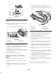
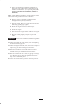
Figure 35
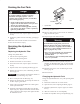
1. 2-3/4 inches (7 cm)
1. Lower the loader arms, stop the engine, and remove
the key.
2. Lift/support the side of the unit to be worked on so that
the track is off of the ground.
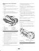
3. Remove the locking bolt and nut (Fig. 36).
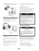
m–4747
1
23
4
Figure 36
1. Locking bolt
2. Tensioning screw
3. Tension tube
4. Tension wheel
4. Using a 1/2 inch drive socket (Fig. 38), turn the
tensioning screw counter-clockwise until the distance
between the tension nut and the back of the tension
tube (Fig. 35) is 2-3/4 inches (7 cm).
5. Align the closest notch in the tension screw to the
locking bolt hole and secure the screw with the locking
bolt and nut (Fig. 36).
6. Lower the traction unit to the ground.
Replacing the Tracks (TX 420, Model
22306)
When the tracks are badly worn, replace them.
1. Lower the loader arms, stop the engine, and remove
the key.
2. Lift/support the side of the unit to be worked on so that
the track is 3 to 4 inches (7.6 to 10 cm) off of the
ground.
3. Remove the locking bolt and nut (Fig. 36).
4. Using a 1/2 inch drive socket, release the drive tension
by turning the tensioning screw clockwise (Fig. 36
and 37).
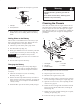
m–6782
1
5
3
8
6
2
4
7
Figure 37
1. Track
2. 1/2 inch socket
3. Tension wheel
4. Fork tube
5. Track lug
6. Drive sprocket
7. Sprocket spacer
8. Road wheels
5. Push the tension wheel toward the rear of the unit to
move the fork tube against the frame (Fig. 37). (If it
does not touch the frame, continue turning the
tensioning screw until it does.)
6. Begin removing the track at the top of the tension
wheel, peeling it off of the wheel while rotating the
track forwards.
7. When the track is off of the tension wheel, remove it
from the drive sprocket and road wheels (Fig. 37).
8. Beginning at the drive sprocket, coil the new track
around the sprocket, ensuring that the lugs on the track
fit between the spacers on the sprocket (Fig. 37).
9. Push the track under and between the road wheels
(Fig. 37).
10. Starting at the bottom of the tension wheel, install the
track around the wheel by rotating the track rearward
while pushing the lugs into the wheel.
11. Turn the tensioning screw counter-clockwise until the
distance between the tension nut and the back of the
fork tube (Fig. 35) is 2-3/4 inches (7 cm).
12. Align the closest notch in the tension screw to the
locking bolt hole and secure the screw with the locking
bolt and nut.
13. Lower the traction unit to the ground.
14. Repeat steps 2 through 20 to replace the other track.