
Operator's Manual


Operation
16
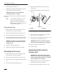
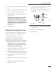
To tilt the attachment rearward, slowly move the lever
to the left (Fig. 9).
To lower the loader arms, slowly move the lever
forward (Fig. 9).
To raise the loader arms, slowly move the lever
rearward (Fig. 9).
You can also push the lever fully forward into a
detent position (Fig. 9) to release the loader arms so
that the attachment rests on the ground. This allows
attachments such as the leveler and the hydraulic
blade to follow the contours of the ground (i.e., float)
when grading.
m–4666
1
2
43
5
Figure 9
1. Lower the loader arms
2. Raise the loader arms
3. Tilt the attachment
rearward
4. Tilt the attachment forward
5. Detent (Float) position
By moving the lever to an intermediate position (such
as, forward and left), you can move the loader arms
and tilt the attachment at the same time.
Auxiliary Hydraulics Lever
To operate a hydraulic attachment in the forward
direction, rotate the auxiliary hydraulics lever
rearward and pull it down to the reference bar
(Fig. 10, number 2).
To operate a hydraulic attachment in reverse
direction, rotate the hydraulics lever rearward, then
move it left into the upper slot (Fig. 10, number 3).
To operate the auxiliary hydraulics in the reverse
direction using a detent position, rotate the lever
rearward, then move it left into the middle slot
(Fig. 10, Number 4). Only use the detent position for
attachments that require it for operation, such as the
Cement Bowl. To determine if an attachment requires
the detent position, refer to the attachment operator’s
manual.
If you release the lever while in either the forward
position or upper reverse position, the lever will
automatically return to the neutral position
(Fig. 10, Number 1). If it is in the detent position, it
will remain there until you pull it out of the slot.
m–4665
12
3
4
Figure 10
1. Neutral
2. Forward flow hydraulics
3. Reverse flow hydraulics
4. Reverse flow
hydraulics—detent
position
Parking Brake Lever
To set the parking brake, pull the brake lever rearward
and then push it to the left, hooking it into the notch
(Fig. 11).
Note: The traction unit may roll slightly
before the brakes engage in the drive
sprocket.
m–4667
Figure 11