
Operator's Manual


Operation
19
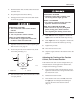
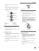
5. Remove the hairpin cotter and clevis pin
securing the cylinder lock to the loader arm
(Fig. 13)
6. Lower the cylinder lock over the cylinder rod
and secure it with the clevis pin and hairpin
cotter (Fig. 13).
m–4672
2
3
1
4
Figure 13
1. Cylinder lock
2. Lift cylinder
3. Clevis pin
4. Hairpin cotter
7. Slowly lower the loader arms until cylinder lock
contacts the cylinder body and rod end.
Removing/Storing the Cylinder Lock
IMPORTANT: Ensure that the cylinder lock
is removed from the rod and fully secured in
the storage position before operating the
traction unit.
1. Start the engine.
2. Raise the loader arms to the fully raised position.
3. Stop the engine.
4. Remove the clevis pin and cotter pin securing
the cylinder lock.
5. Rotate the cylinder lock up to the loader arm and
secure it with the clevis pin and hairpin cotter
(Fig. 13).
6. Lower the loader arms.
Using Attachments
IMPORTANT: If you are using an attachment
with a serial number of 200999999 or earlier,
the manual for the attachment may contain
information specific to the use of the
attachment with other Dingo models, such as
settings for the flow divider control and speed
selector lever and the use of a counterweight
on the traction unit. These systems are built
into the Dingo TX, and you should ignore any
references to them.
Connecting an Attachment
IMPORTANT: Use only Toro-approved
attachments. Attachments can change the
stability and the operating characteristics of
the traction unit. The warranty of the
traction unit may be voided if used with
unapproved attachments.
IMPORTANT: Before installing the
attachment, ensure that the mount plates are
free of any dirt or debris and that the pins
rotate freely.
1. Position the attachment on a level surface with
enough space behind it to accommodate the
traction unit.
2. Start the engine.
3. Tilt the attachment mount plate forward.
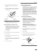
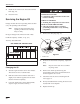
4. Position mount plate into the upper lip of the
attachment receiver plate (Fig. 14).
m–4055
1
2
Figure 14
1. Mount plate 2. Receiver plate