
Operator's Manual


Maintenance
30
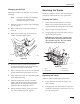
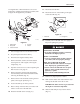
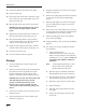
3. Remove the locking bolt and nut (Fig. 30).
m–4747
1
23
4
Figure 30
1. Locking bolt
2. Tensioning screw
3. Fork tube
4. Tension wheel
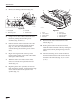
4. Using a 1/2 in. drive socket, release the drive
tension by turning the tensioning screw
clockwise (Fig. 30 and 31).
5. Push the tension wheel toward the rear of the
unit to move the fork tube against the frame
(Fig. 31). (If it does not touch the frame,
continue turning the tensioning screw until it
does.)
6. Begin removing the track at the top of the
tension wheel, peeling it off of the wheel while
rotating the track forwards.
7. When the track is off of the tension wheel,
remove it from the drive sprocket and road
wheels (Fig. 31).
8. Beginning at the drive sprocket, coil the new
track around the sprocket, ensuring that the lugs
on the track fit between the spacers on the
sprocket (Fig. 31).
m–4774
1
5
3
8
6
2
4
7
Figure 31
1. Track
2. 1/2 in. socket
3. Tension wheel
4. Fork tube
5. Track lug
6. Drive sprocket
7. Sprocket spacer
8. Road wheels
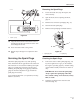
9. Push the track under and between the road
wheels (Fig. 31).
10. Starting at the bottom of the tension wheel,
install the track around the wheel by rotating the
track rearward while pushing the lugs into the
wheel.
11. Turn the tensioning screw counter-clockwise
until the distance between the tension nut and
the back of the fork tube (Fig. 32) is 2 3/4 in.
(7 cm.).