Form No. 3327-243 TX 420 and TX 425 Dingo Compact Utility Loader Model No. 22306—220000001 and Up Model No.
Warning Checking the Hydraulic Fluid . . . . . . . . . . . . . . . Operation . . . . . . . . . . . . . . . . . . . . . . . . . . . . . . . . . . Traction Unit Overview . . . . . . . . . . . . . . . . . . . . Controls . . . . . . . . . . . . . . . . . . . . . . . . . . . . . . . . Starting and Stopping the Engine . . . . . . . . . . . . Stopping the Traction Unit . . . . . . . . . . . . . . . . . Moving a Non-functioning Traction Unit . . . . . . Using the Cylinder Lock . . . . . . . . . . . . . . . . . . .
Read this manual carefully to learn how to operate and maintain your product correctly. Reading this manual will help you and others avoid personal injury and damage to the product. Although we design, produce and market safe, state-of-the-art products, you are responsible for using the product properly and safely. You are also responsible for training persons, who you allow to use the product, about safe operation.
• Slow down and use extra care on hillsides. Be sure to travel in the recommended direction on hillsides. Turf conditions can affect the machine’s stability. • Do not touch parts which may be hot from operation. Allow them to cool before attempting to maintain, adjust, or service. • Slow down and use caution when making turns and when changing directions on slopes. • Check for overhead clearances (i.e. branches, doorways, electrical wires) before driving under any objects and do not contact them.
• Do not operate near drop-offs, ditches, or embankments. The traction unit could suddenly turn over if a track goes over the edge of a cliff or ditch, or if an edge caves in. • Keep the traction unit free of grass, leaves, or other debris build-up. Clean up oil or fuel spillage. Allow the traction unit to cool before storing. • Use extra care when handling gasoline and other fuels. They are flammable and vapors are explosive. • Do not operate on wet grass. Reduced traction could cause sliding.
Slope Chart M 4402 6
Safety and Instruction Decals Safety decals and instructions are easily visible to the operator and are located near any area of potential danger. Replace any decal that is damaged or lost.
Assembly Activating the Battery 105-8404 Warning Battery posts, terminals, and related accessories contain lead and lead compounds, chemicals known to the State of California to cause cancer and reproductive harm. Wash hands after handling. 80-8290 The traction unit is shipped with a dry battery. Purchase bulk electrolyte with 1.260 specific gravity from a local battery supply outlet. 1. Open the rear access cover; refer to Opening the Rear Access Cover, page 21. 2.
8. Tilt the top of the battery rearward and slide it into the traction unit. 4. Remove filler caps from the battery. Slowly pour electrolyte into each cell until the electrolyte level is up to the lower part of the tube (Fig. 2). Important Do not allow the battery posts to touch the frame or hydraulic lines or it may cause sparks. 1 9. Secure the battery in chassis with the clamp, bolts, and nuts removed previously (Fig. 1). 10.
TX 425, Model 22307 Reach—fully raised (with narrow bucket) 22 inches (55 cm) Height to hinge pin (narrow bucket in the highest position) 66 inches (168 cm) Width 41 inches (104 cm) Length 71 inches (180 cm) Height 43 inches (109 cm) Weight 2007 lbs (910 Kg) Operating capacity 500 lbs (227 Kg) Attachments Tipping capacity 1480 lbs (671 Kg) Wheelbase 31.2 inches (79 cm) Dump height (with narrow bucket) 47 inches (119 cm) Many attachments are available for use with the traction unit.
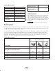
TX 425, Model 22307 Maximum Recommended Slope when Operating with: Front Uphill Rear Uphill Side Uphill 12° 20° 23° A 25° 25° 25° B 22° 22° 22° C 18° 16° 16° D 10° 10° 10° E 5° 5° 5° Configuration Traction unit without attachment Traction unit with an attachment rated with one of the following stability ratings for each slope position: Before Operating Before operating, check the fuel and oil level, and remove debris from the traction unit.
Add the correct amount of gas stabilizer/conditioner to the gas. Danger Note: A fuel stabilizer/conditioner is most effective when mixed with fresh gasoline. To minimize the chance of varnish deposits in the fuel system, use fuel stabilizer at all times. In certain conditions, gasoline is extremely flammable and highly explosive. A fire or explosion from gasoline can burn you and others and can damage property. • Fill the fuel tank outdoors, in an open area, when the engine is cold.
Use 10W-30 detergent, diesel engine oil (API service CH-4 or higher). 1 1. Remove the attachment, if one is installed; refer to Removing an Attachment, page 19. 2 m–4745 2. Park the traction unit on a level surface, lower the loader arms, and fully retract the tilt cylinder. Figure 5 1. Filler cap 3. Stop the engine, remove the key, and allow the engine to cool. 2. Valve cover 4. Open the hood; refer to Opening the Hood, page 21. 9.
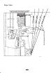
Operation Traction Unit Overview Figure 7 contains a front and back view of the traction unit. Familiarize yourself with all of the traction unit components listed in Figure 7. 6 5 11 10 7 4 8 3 14 2 m–4732 1 m 5241 9 13 12 Figure 7 1. 2. 3. 4. Track Track adjustment chamber Lift cylinder Cylinder lock 5. 6. 7. 8. Loader arms Hood Auxiliary hydraulic couplers Tilt cylinder 9. Mount plate 10. Tie-down/lift loop 11. Control panel 12. Rear access cover 13. Fuel tank 14.
Key Switch Loader Arm/Attachment Tilt Lever The key switch, used to start and stop the engine, has three positions: off, run, and start. To tilt the attachment forward, slowly move the lever to the right (Fig. 10). To start the engine, rotate the key to the start position. Release the key when engine starts and it will move automatically to the run position. To tilt the attachment rearward, slowly move the lever to the left (Fig. 10). To stop the engine, rotate the key to the off position.
Note: The traction unit may roll slightly before the brakes engage in the drive sprocket. 2 2 1 m-5238 Figure 11 1. Loader valve lock m–5918 2. Loader arm/attachment tilt lever Figure 13 To release the brake, pull the lever rearward and right, out of the notch, and then push it forward. Auxiliary Hydraulics Lever To operate a hydraulic attachment in the forward direction, rotate the auxiliary hydraulics lever rearward and pull it down to the reference bar (Fig. 12, number 2).
Moving a Non-functioning Traction Unit Note: A warm or hot engine may not require choking. 4. Turn the ignition key to the start position. When the engines starts, release the key. Important Do not tow or pull the traction unit without first opening the tow valves, or the hydraulic system will be damaged Important Do not engage the starter for more than 10 seconds at a time. If the engine fails to start, allow a 30 second cool-down period between attempts.
Connecting an Attachment 5. Lower the cylinder lock over the cylinder rod and secure it with the clevis pin and hairpin cotter (Fig. 15). Important Use only Toro-approved attachments. Attachments can change the stability and the operating characteristics of the traction unit. The warranty of the traction unit may be voided if used with unapproved attachments. 1 3 Important Before installing the attachment, ensure that the mount plates are free of any dirt or debris and that the pins rotate freely.
4. Remove the protective covers from the hydraulic couplers on the traction unit. Warning 5. Ensure that all foreign matter is cleaned from the hydraulic connectors. If you do not fully seat the quick attach pins through the attachment mount plate, the attachment could fall off of the traction unit, crushing you or bystanders. 6. Push the attachment male connector into the female connector on the traction unit.
1. Lower the loader arms. 5. If the attachment uses hydraulics, slide the collar back on the hydraulic couplers and disconnect them. 2. Stop the engine. 6. Install the protective covers onto the hydraulic couplers on the traction unit. 3. Set the parking brake. 4. Secure the traction unit to the trailer with chains or straps using the tie-down/lift loops (Fig. 7) to secure the rear of the traction unit and the loader arms/mount plate to secure the front of the traction unit. 7.
1More often in dusty, dirty conditions. oil after the first 50 operating hours. 3Change the hydraulic filter after the first 8–10 operating hours 4For severe duty or rental applications, change every 100 operating hours. 5For severe duty or rental applications, change every 200 operating hours. 6Check the hydraulic fluid level before using the traction unit for the first time 2Change Important Refer to your engine operator’s manual for additional maintenance procedures.
2. Swing the rear access cover to the right (Fig. 20). 4. Turn the tabs and fold them down to lock the screen in place (Fig. 21). Removing the Front Screen Caution If the engine has been running the heat shield will be very hot and could burn you. m–4670 Allow the traction unit cool completely before touching the heat shield. Figure 20 1. Open the hood and remove both side screens. Closing the Rear Access Cover 2. Loosen the bolts securing the front weight (Fig. 22). 1.
7. Remove the front screen. 1 4 1 1 2 2 1 2 m–4770 3 Figure 25 m–5921 1. Traction rod 2. Jam nut Figure 24 1. Nut 2. Oil cooler 6. Start the traction unit and set the throttle to about 1/3 open position. 3. Front screen 4. Shoulder bolts Warning 8. When finished, install the front screen with the 4 bolts removed previously. 9. Install the oil cooler to the front screen with the 2 shoulder bolts, double washer, and nuts removed previously.
7. Install the left panel cover. m–4664 Servicing the Air Cleaner Foam Pre-filter: Clean every 25 operating hours. 1 1 Paper Filter: Clean every 25 operating hours. Replace after every 100 operating hours. Figure 26 1. Jam nut and set screw Note: Service the air cleaner more frequently if operating conditions are extremely dusty or sandy. 5. Repeat steps 1 through 4 until the traction unit drives straight in the full forward position. Removing the Foam and Paper Filters 1.
Servicing the Engine Oil 3. Put one or two ounces of oil on the pre-filter (Fig. 29). 2 Change oil after the first 50 operating hours and then every 100 operating hours thereafter. 1 Note: Change oil more frequently when operating conditions are extremely dusty or sandy. m–1213 Figure 29 1. Foam element Oil Type: Detergent oil (API service SG, SH, SJ, or higher) 2. Oil Crankcase Capacity: w/filter, 2.1 qt. (2 l) 4. Squeeze the pre-filter to distribute the oil. Viscosity: See table below 5.
1 m–4751 Figure 31 1. Oil drain valve 1 5. When the oil has drained completely, replace the plug. m–1256 Figure 32 Note: Dispose of the used oil at a certified recycling center. 1. Oil filter 6. Remove the oil fill cap and slowly pour approximately 80% of the specified amount of oil in through the valve cover. 4. Pour new oil of the proper type through the center hole of the filter. Stop pouring when the oil reaches the bottom of the threads. 7.
1. Lower the loader arms, stop the engine, and remove the key. Important Ensure that you only use high-pressure water to wash the track area. Do not use a high-pressure washer to clean the rest of the traction unit. High-pressure washing can damage the electrical system and hydraulic valves or deplete grease. 2. Lift/support the side of the unit to be worked on so that the track is off of the ground. 3. Remove the locking bolt and nut (Fig. 35).
1 1. Lower the loader arms, stop the engine, and remove the key. 3 4 2. Lift/support the side of the unit to be worked on so that the track is three to four inches (7.6 to 10 cm.) off of the ground. 8 3. Remove the locking bolt and nut (Fig. 35). 4. Using a 1/2 in. drive socket, release the drive tension by turning the tensioning screw clockwise (Fig. 35 and 37). 5 7 6 m–4774 1 2 Track 1/2 in. socket Tension wheel Fork tube 5. 6. 7. 8. 5 3 Figure 36 1. 2. 3. 4.
3. Bend the side electrode (Fig. 39) if the gap is not correct. 14. Lower the traction unit to the ground. Servicing the Spark Plugs 2 3 1 Check the spark plugs after every 200 operating hours. Ensure that the air gap between the center and side electrodes is correct before installing each spark plug. Use a spark plug wrench for removing and installing the spark plugs and a gapping tool/feeler gauge to check and adjust the air gap. Install new spark plugs if necessary. 0.030 in. (0.
9. Remove the clamp blocking fuel flow and open the fuel valves. 10. Secure the tank cap. 11. Replace the side screen and close the hood. m–4056 Draining the Fuel Tank Figure 41 Danger 4. Pump grease into the fittings until grease begins to ooze out of the bearings (approximately 3 pumps). In certain conditions, gasoline is extremely flammable and highly explosive. A fire or explosion from gasoline can burn you and others and can damage property. 5. Wipe up any excess grease.
7. Apply a thin coat hydraulic fluid to the rubber gasket on the replacement filter. 2. Open the hood, refer to Opening the Hood, page 21. 3. Install the cylinder lock, stop the engine, and remove the key. 8. Install the replacement hydraulic filter onto the filter adapter (Fig. 43). Tighten it clockwise until the rubber gasket contacts the filter adapter, then tighten the filter an additional 3/4 turn. 4. Allow the traction unit to cool completely. 5. Remove the hydraulic tank cap and dipstick (Fig.
9. Fill the hydraulic tank with approximately 12 gal. (45.4 l) of 10W-30 detergent, diesel engine oil (API service CH-4 or higher); refer to Checking Hydraulic Fluid, page 13. Checking the Electrolyte Level 10. Start the engine and let it run for a few minutes. Important Do not allow the electrolyte to get below the plates. (Fig. 46). 1. Open covers to see into the cells. The electrolyte must be up to the lower part of the tube (Fig. 46). 11. Stop the engine. 1 12.
8. Loosen the tank cap to relieve pressure. Warning 9. Place a clamp on the fuel line, two inches from where it comes out of the fuel tank. Charging the battery produces gasses that can explode. 10. Slide the fuel tank to the rear (Fig. 47). 11. Disconnect the fuel line. Never smoke near the battery and keep sparks and flames away from battery. 12. Disconnect the two wires leading to the right side of the tank (Fig. 48).
A. Add a petroleum based stabilizer/conditioner to fuel in the tank. Follow mixing instructions from stabilizer manufacturer. (1 oz. per gallon). Do not use an alcohol based stabilizer (ethanol or methanol). 20. Slide the tank all the way into the traction unit. Important The fuel line and wires must be away from the engine pulleys and the frame. 21. Replace the rear panel and secure it with the six bolts and nuts removed previously (Fig. 47).
Troubleshooting PROBLEM Starter does not crank POSSIBLE CAUSES CORRECTIVE ACTION 1. Battery is dead. 1. Charge the battery. 2. Electrical connections are corroded or loose. 2. Check electrical connections for good contact. 3. Relay or switch is defective. 3. Contact Authorized Service Dealer. 1. Fuel tank is empty. 1. Fill fuel tank with gasoline. 2. Choke is not on. 2. Move choke lever fully forward. 3. Air cleaner is dirty. 3. Clean or replace air cleaner element. 4.
The Toro Dingo Product Line Warranty A One-Year Limited Warranty Conditions and Products Covered The Toro Company and its affiliate, Toro Warranty Company, pursuant to an agreement between them, jointly warrant your Toro Dingo Product (“Product”) to be free from defects in materials or workmanship.