Form No. 3354-650 Rev B Dingo® TX 420 and TX 425 Compact Utility Loader Model No. 22306—Serial No. 260000001 and Up Model No. 22307—Serial No. 260000001 and Up Register your product at www.Toro.
Warning Service Dealer or Toro Customer Service and have the model and serial numbers of your product ready. The model and serial numbers are stamped into a plate mounted under the hood near the belt drive. Write the numbers in the space provided. CALIFORNIA Proposition 65 Warning The engine exhaust from this product contains chemicals known to the State of California to cause cancer, birth defects, or other reproductive harm. Model No. Serial No.
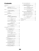
Contents Drive System Maintenance......................... 33 Servicing the Tracks........................... 33 Controls System Maintenance.................... 36 Adjusting the Traction Control Alignment ......................... 37 Adjusting the Traction Control Neutral Position ................ 37 Adjusting the Tracking of the Traction Control, Full Forward Position ............... 38 Hydraulic System Maintenance .................. 38 Replacing the Hydraulic Filter ............
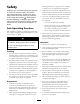
Safety hearing protection. Long hair, loose clothing or jewelry may get tangled in moving parts. Improper use or maintenance by the operator or owner can result in injury. To reduce the potential for injury, comply with these safety instructions and always pay attention to the safety alert symbol , which means: Caution, Warning, or Danger—personal safety instruction. Failure to comply with the instruction may result in personal injury or death.
• Never carry passengers and keep pets and bystanders away. • Slow down and use caution when making turns and crossing roads and sidewalks. • Do not operate the machine under the influence of alcohol or drugs. • Use care when loading or unloading the machine into a trailer or truck. • Use care when approaching blind corners, shrubs, trees, or other objects that may obscure vision. • Read all attachment manuals. • Ensure that the area is clear of other people before operating the traction unit.
• Avoid starting or stopping on a slope. If the traction unit loses traction, proceed slowly, straight down the slope. • Avoid turning on slopes. If you must turn, turn slowly and keep the heavy end of the traction unit uphill. • Do not operate near drop-offs, ditches, or embankments. The traction unit could suddenly turn over if a track goes over the edge of a cliff or ditch, or if an edge caves in. • Do not operate on wet grass. Reduced traction could cause sliding.
hydraulic fluid. Use cardboard or paper to find hydraulic leaks; never use your hands. Hydraulic fluid escaping under pressure can penetrate skin and cause injury requiring surgery within a few hours by a qualified surgeon or gangrene may result.
Slope Chart 8
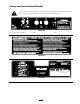
Safety and Instructional Decals Safety decals and instructions are easily visible to the operator and are located near any area of potential danger. Replace any decal that is damaged or lost. 108-4658 1. Operator’s Manual location. 2. Fast 3.
7-9309 1. Warning—read the Operator’s Manual for information on charging the battery; contains lead; do not discard. 2. Read the Operator’s Manual. HYDRAULIC COUPLERS HYDRAULIC COUPLERS MAY BE HOT. MAY BE HOT. PROTECTIVE WEAR SHOULD BE WORNPROTECTIVE WEAR SHOULD BE WORN WHEN CONNECTING COUPLERS. WHEN CONNECTING COUPLERS.
108-4670 108-4671 93-9084 1. Lift point 2.
Setup Charging the battery produces gasses that can explode. Step 1 Never smoke near the battery and keep sparks and flames away from battery. 3. When the battery is fully charged, unplug the charger from the electrical outlet, then disconnect the charger leads from the battery posts (Figure 2). Charging the Battery No Parts Required 4. Close the rear access cover.
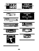
Product Overview Figure 3 1. 2. 3. 4. Track Track adjustment chamber Lift cylinder Cylinder lock 5. 6. 7. 8. Loader arms 9. Mount plate Hood 10. Tie-down/lift loop Auxiliary hydraulic couplers 11. Control panel 12. Rear access cover Tilt cylinder Controls 13. Fuel tank 14. Reverse safety plate To start the engine, rotate the key to the start position. Release the key when engine starts and it will move automatically to the run position.
Traction Control To move forward, move the traction control forward. To move rearward, move the traction control rearward (Figure 5). To turn, rotate the traction control in the desired direction (Figure 5). The farther you move the traction control in any direction, the faster the traction unit will move in that direction. To stop, release the traction control. Figure 6 1. Lower the loader arms 2. Raise the loader arms 3. Tilt the attachment rearward 4. 5.
Parking Brake Lever procedures based on a 100, 200, or 400 hour schedule. These reminders come on starting three hours prior to the service interval time and flash at regular intervals for six hours. To set the parking brake, push the brake lever forward and to the left and then pull it rearward (Figure 8). Note: The traction unit may roll slightly before the brakes engage in the drive sprocket. Figure 8 To release the brake, push the lever forward and then right, into the notch.
Specications Note: Specifications and design are subject to change without notice. TX 420, Model 22306 Width 34 inches (86 cm) Length 71 inches (180 cm) Height 43 inches (109 cm) Weight 1880 lb (853 Kg) Operating capacity 500 lb (227 Kg) Tipping capacity 1530 lb (694 Kg) Wheelbase 31.
Stability Data The following tables list the maximum slope recommended for the traction unit in the positions listed in the tables. Slopes over the listed degree may cause the traction unit to become unstable. The data in the tables assume that the loader arms are fully lowered; raised arms may affect the stability. In each attachment manual is a set of three stability ratings, one for each hill position.
Operation In certain conditions during fueling, static electricity can be released causing a spark which can ignite the gasoline vapors. A fire or explosion from gasoline can burn you and others and can damage property. Note: Determine the left and right sides of the machine from the normal operating position. Important: Before operating, check the fuel and oil level, and remove debris from the traction unit. Also, ensure that the area is clear of people and debris.
Note: A fuel stabilizer/conditioner is most effective when mixed with fresh gasoline. To minimize the chance of varnish deposits in the fuel system, use fuel stabilizer at all times. Filling the Fuel Tank 1. Park the traction unit on a level surface, lower the loader arms, and stop the engine. 2. Remove the key and allow the engine to cool. 3. Clean around the fuel tank cap and remove it. Figure 10 4. Add unleaded gasoline to the fuel tank, until the level is just below the bottom of the filler neck. 1.
Important: If the engine is run at high speeds when the hydraulic system is cold (i.e., when the ambient air temperature is near freezing or lower), hydraulic system damage could occur. When starting the engine in cold conditions, allow the engine to run in the middle throttle position for 2 to 5 minutes before moving the throttle to fast (rabbit). Note: If outdoor temperature is below freezing, store the traction unit in a garage to keep it warmer and aid in starting. Figure 11 1. Filler neck cap 2.
2. Open the rear access cover. 3. Using a wrench, turn the tow valves on the hydraulic pumps twice counter-clockwise (Figure 12). Figure 13 1. 2. Cylinder lock Lift cylinder 3. 4. Clevis pin Hairpin cotter 5. Lower the cylinder lock over the cylinder rod and secure it with the clevis pin and hairpin cotter (Figure 13). 6. Slowly lower the loader arms until cylinder lock contacts the cylinder body and rod end. Figure 12 1. Left tow valve (right track) 2.
Using Attachments Important: The attachment should be raised enough to clear the ground, and the mount plate should be tilted all the way back. Important: If you are using an attachment with a serial number of 200999999 or earlier, the manual for the attachment may contain information specific to the use of the attachment with other Dingo models, such as settings for the flow divider control and speed selector lever and the use of a counterweight on the traction unit.
Connecting the Hydraulic Hoses 8. Confirm that the connection is secure by pulling on the hoses. If the attachment requires hydraulics for operation, connect the hydraulic hoses as follows: 1. Stop the engine. 2. Move the auxiliary hydraulics lever forward, backward, and back to neutral to relieve pressure at the hydraulic couplers. 3. Move the auxiliary hydraulics lever into the reverse position. 4. Remove the protective covers from the hydraulic couplers on the traction unit. 5.
Maintenance Note: Determine the left and right sides of the machine from the normal operating position. Recommended Maintenance Schedule(s) Maintenance Service Interval Maintenance Procedure After the rst 8 operating hours • Replace the hydraulic lter. After the rst 50 operating hours Before each use or daily • Change the engine oil. • Check and adjust the track tension. • • • • • Check the engine oil level. Grease the traction unit. Check the condition of and clean the tracks.
If you leave the key in the ignition switch, someone could accidently start the engine and seriously injure you or other bystanders. Remove the key from the ignition and disconnect the wire from the spark plug before you do any maintenance. Set the wire aside so that it does not accidentally contact the spark plug. Premaintenance Procedures Before opening any of the covers, stop the engine and remove the key. Allow the engine to cool before opening any covers Opening the Hood 1.
Installing the Side Screens Slide the side screens into place in the slots in the front screen and frame. Removing the Front Screen If the engine has been running the heat shield will be very hot and could burn you. Figure 18 Allow the traction unit cool completely before touching the heat shield. 1. Hand knob 2. Tilt the rear access cover down and remove to access the internal components (Figure 18). 1. Open the hood and remove both side screens. 2.
11. Tighten the bolts securing the front weight (Figure 20). 12. Install the side screens and close the hood. Lubrication Greasing the Traction Unit Grease all pivot joints every 8 operating hours and immediately after every washing. Grease Type: General-purpose grease. 1. Lower the loader arms and stop the engine. Remove the key. Figure 21 1. Front screen 2. Bolts (left side bolt not shown) 2. Clean the grease fittings with a rag. 3. Connect a grease gun to each fitting (Figure 23 and Figure 24). 6.
Figure 24 4. Pump grease into the fittings until grease begins to ooze out of the bearings (approximately 3 pumps). Figure 25 5. Wipe up any excess grease. 1. 2. 3. 4. 5. Engine Maintenance Servicing the Air Cleaner Knob Air cleaner cover Cover nut Spacer Cover 6. 7. 8. 9. Foam pre-lter Paper lter Rubber seal Air cleaner base 5. Carefully slide the foam pre-filter off of the paper element (Figure 25). 6. Unscrew the cover nut and remove the cover, spacer and paper filter (Figure 25).
5. Lightly tap the paper filter on a flat surface to remove dust and dirt (Figure 27). Crankcase Capacity: w/filter, 2.1 qt. (2 l) Viscosity: See table below Figure 27 1. Paper element 2. Rubber seal Figure 28 6. Inspect the paper filter for tears, an oily film, and damage to the rubber seal. Important: Never clean the paper element with pressurized air or liquids, such as solvent, gas, or kerosene. Replace the paper element if it is damaged, or cannot be cleaned thoroughly (i.e.
5. When the oil has drained completely, replace the plug. 6. 7. 8. 9. 7. Install the replacement oil filter to the filter adapter. Turn the oil filter clockwise until the rubber gasket contacts the filter adapter, then tighten the filter an additional 1/2 turn. Note: Dispose of the used oil at a certified recycling center. Remove the oil fill cap and slowly pour approximately 80% of the specified amount of oil in through the valve cover.
Important: Never clean the spark plugs. Always replace the spark plugs when they have a black coating, worn electrodes, an oily film, or cracks. Figure 33 1. 3. 2. Hose clamp 5. Squeeze the ends of the hose clamps together and slide them away from the filter (Figure 33). Figure 32 1. Center electrode insulator 2. Side electrode Filter Air gap (not to scale) 6. Place a drain pan under the fuel lines to catch any leaks, then remove the filter from the fuel lines. 2.
1. Lower the loader arms, stop the engine, and remove the key. 2. Syphon the gasoline from the tank using a pump type syphon. 2 Note: Now is the best time to install a new fuel filter because the fuel tank is empty. 3 Electrical System Maintenance 1 G003794 Figure 34 Servicing the Battery 1. Filler caps 2. Upper line Warning 3. Lower line 4. If the electrolyte is low, add the required amount of distilled water; refer to Adding Water to the Battery.
Important: Do not overfill the battery because electrolyte (sulfuric acid) can cause severe corrosion and damage to the chassis. 5. Wait five to ten minutes after filling the battery cells. Add distilled water, if necessary, until the electrolyte level is up to the Upper line (Figure 34) on the battery case. 6. Install the battery filler caps. disconnect the charger leads from the battery posts (Figure 35). 5. Replace the battery cover.
Adjusting the Track Tension back of the tension tube (Figure 37) is 2-3/4 inches (7 cm). 5. Align the closest notch in the tension screw to the locking bolt hole and secure the screw with the locking bolt and nut (Figure 38). 6. Lower the traction unit to the ground. Check and adjust the track tension after the first 50 operating hours and every 100 operating hours thereafter. There should be 2-3/4 inches (7 cm) between the tension nut and the back of the tension tube (Figure 37).
7. When the track is off of the tension wheel, remove it from the drive sprocket and road wheels (Figure 39). 8. Beginning at the drive sprocket, coil the new track around the sprocket, ensuring that the lugs on the track fit between the spacers on the sprocket (Figure 39). 9. Push the track under and between the road wheels (Figure 39). 10. Starting at the bottom of the tension wheel, install the track around the wheel by rotating the track rearward while pushing the lugs into the wheel. 11.
16. Torque the nut to 300 ft-lb (407 N⋅m). 17. Turn the tensioning screw counter-clockwise until the distance between the tension nut and the back of the tension tube (Figure 37) is 2-3/4 inches (7 cm). 18. Align the closest notch in the tension screw to the locking bolt hole and secure the screw with the locking bolt and nut. 19. Repeat steps 2 through 18 to replace the other track. Figure 42 20. Lower the traction unit to the ground. 1. Road wheel 2. Gasket 3.
Adjusting the Traction Control Alignment If the traction control bar does not rest flush and square with the reference bar when in the full backward position, immediately complete the following procedure: 1. Park the traction unit on a flat surface and lower the loader arm. Figure 45 2. Stop the engine and remove the key. 6. Tighten the flange nut and bolt in the traction control stem. 3. Pull straight back on the traction control so the front of the control contacts the reference bar (Figure 43).
When the traction unit is running, you could be caught and injured in moving parts or burned on hot surfaces. Stay away from pinch points, moving parts, and hot surfaces when adjusting the running traction unit. 5. If the left track moves, lengthen or shorten the right traction rod until the track stops moving. 6. If the right track moves, lengthen or shorten the left traction rod until the track stops moving. Figure 47 1. Set screw 2. Jam nut 3. Stop 7. Tighten the jam nuts. 8.
Changing the Hydraulic Fluid Change the hydraulic fluid after every 400 operating hours or yearly. 1. Position the traction unit on a level surface. 2. Open the hood. 3. Install the cylinder lock, stop the engine, and remove the key. 4. Allow the traction unit to cool completely. Figure 48 5. Remove the hydraulic tank cap and dipstick (Figure 49). 1. Hydraulic lter Note: The filler cap is behind the front screen. If you want to improve your access to it, remove the screen. 5.
Hydraulic fluid escaping under pressure can penetrate skin and cause injury. Fluid injected into the skin must be surgically removed within a few hours by a doctor familiar with this form of injury or gangrene may result. • Keep your body and hands away from pin hole leaks or nozzles that eject high pressure hydraulic fluid. • Use cardboard or paper to find hydraulic leaks, never use your hands. Cleaning Figure 50 1. Drain plug Removing Debris from the Traction Unit 7.
Cleaning the Chassis Over time, the chassis under the engine collects dirt and debris that must be removed. Using a flashlight, open the hood and inspect the area under the engine on a regular basis. When the debris is 1 to 2 inches deep, complete the following procedure (refer to Figure 51 throughout this procedure): Figure 52 1. Black wire 2. Orange wire 13. Carefully remove the tank and set it upright to keep from spilling the gasoline.
Important: The fuel line and wires must be away from the engine pulleys and the frame. 21. Replace the rear panel and secure it with the six bolts and nuts removed previously (Figure 51). 22. Secure the battery tray with the bolts and washers removed previously. 23. Install the side weights with the bolts, washers, and lock washers removed previously (Figure 51). 24. Close the rear access cover. 25. Lower the traction unit to the ground.
Storage B. Run the engine to distribute conditioned fuel through the fuel system (5 minutes). 1. Lower the loader arms, stop the engine, and remove the key. C. Stop the engine, allow it to cool and drain the fuel tank using a pump type syphon. 2. Remove dirt and grime from the external parts of the entire traction unit, especially the engine. Clean dirt and chaff from the outside of the engine cylinder head fins and blower housing. D. Restart the engine and run it until it stops. E. Choke the engine. F.
Troubleshooting Problem Possible Cause The starter does not crank 1. The battery is discharged. 2. The electrical connections are corroded or loose. 3. The relay or switch is damaged. The engine will not start, starts hard, or fails to keep running. 1. The fuel tank is empty. 2. 3. 4. 5. 6. 7. Engine loses power. Corrective Action 1. Charge the battery or replace it. 2. Check the electrical connections for good contact. 3. Contact your Authorized Service Dealer. 1. Fill the fuel tank with gasoline.
Problem The engine overheats. Possible Cause Corrective Action 1. The engine load is excessive. 2. The oil level in crankcase is low. 3. The cooling ns and air passages under the engine blower housing are plugged. 1. Reduce ground speed. Abnormal vibration. 1. The engine mounting bolts are loose. 1. Tighten the engine mounting bolts. The traction unit does not drive. 1. The parking brake is on. 2. Check and add oil to the crankcase. 3.
Schematics Electrical Schematic (Rev.
Hydraulic Schematic (Rev.
Evaporative Emission Control Warranty Statement California Evaporative Emission Control Warranty Statement Your Warranty Rights and Obligations Introduction The California Air Resources Board and The Toro® Company are pleased to explain the evaporative emission control system’s warranty on your 2006 model year equipment. In California, new equipment that use small off-road engines must be designed, built, and equipped to meet the State’s stringent anti-smog standards.
The Toro Dingo® Product Line Warranty A One-Year Limited Warranty Conditions and Products Covered The Toro® Company and its afliate, Toro Warranty Company, pursuant to an agreement between them, jointly warrant your Toro Dingo Product (“Product”) to be free from defects in materials or workmanship.