
Operator's Manual


16
Operation
Traction Unit Overview
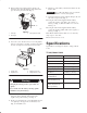
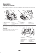
Figure 7 contains a front and back view of the traction unit. Familiarize yourself with all of the traction unit components
listed in Figure 7.
1
2
3
4
6
7
8
9
10
11
12
13
m–4732
5
14
m5241
Figure 7
1. Track
2. Track adjustment chamber
3. Lift cylinder
4. Cylinder lock
5. Loader arms
6. Hood
7. Auxiliary hydraulic couplers
8. Tilt cylinder
9. Mount plate
10. Tie-down/lift loop
11. Control panel
12. Rear access cover
13. Fuel tank
14. Reverse safety plate
Note: Determine the left and right sides of the machine by standing in the operator’s position.
Controls
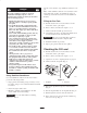
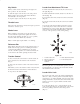
Become familiar with all the controls (Fig. 8) before you
start the engine and operate the traction unit.
5
9
6
7
10
121
3
11
8
4
2
m524
0
Figure 8
1. Traction control
2. Loader arm/attachment tilt
lever
3. Auxiliary hydraulics lever
4. Reference bar
5. Throttle lever
6. Choke lever
7. Fuel gauge
8. Hydraulic oil temperature
light
9. Hour meter/tachometer
10. Key switch
11. Parking brake lever
12. Loader valve lock