
Operator's Manual


17
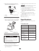
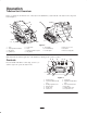
Key Switch
The key switch, used to start and stop the engine, has
three positions: off, run, and start.
To start the engine, rotate the key to the start position.
Release the key when engine starts and it will move
automatically to the run position.
To stop the engine, rotate the key to the off position.
Throttle Lever
Move the control forward to increase the engine speed and
rearward to decrease speed.
Choke Lever
Before starting a cold engine, move the choke lever
forward. After the engine starts, regulate the choke to
keep the engine running smoothly. As soon as possible,
move the choke lever all the way rearward.
Note: A warm engine requires little or no choking.
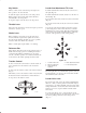
Reference Bar
When driving the traction unit, use the reference bar as a
handle and a leverage point for controlling the traction
control and the auxiliary hydraulics lever. To ensure
smooth, controlled operation, do not take both hands off
of the reference bar while operating the traction unit.
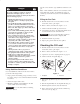
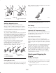
Traction Control
To move forward, move the traction control forward. To
move rearward, move the traction control rearward
(Fig. 9).
To turn, rotate the traction control in the desired direction
(Fig. 9).
The farther you move the traction control in any direction,
the faster the traction unit will move in that direction.
To stop, release the traction control.
m–4664
Figure 9
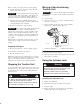
Loader Arm/Attachment Tilt Lever
To tilt the attachment forward, slowly move the lever to
the right (Fig. 10).
To tilt the attachment rearward, slowly move the lever to
the left (Fig. 10).
To lower the loader arms, slowly move the lever forward
(Fig. 10).
To raise the loader arms, slowly move the lever rearward
(Fig. 10).
You can also push the lever fully forward into a detent
position (Fig. 10) to release the loader arms so that the
attachment rests on the ground. This allows attachments
such as the leveler and the hydraulic blade to follow the
contours of the ground (i.e., float) when grading.
m–4666
1
2
43
5
Figure 10
1. Lower the loader arms
2. Raise the loader arms
3. Tilt the attachment
rearward
4. Tilt the attachment forward
5. Detent (Float) position
By moving the lever to an intermediate position (such as,
forward and left), you can move the loader arms and tilt
the attachment at the same time.
Loader Valve Lock
The loader valve lock secures the loader arm/attachment
tilt lever so that you cannot push it forward. This helps to
ensure that no one will accidentally lower the loader arms
during maintenance. Secure the loader arms with the lock
anytime you need to stop the machine with the loader
arms raised.
To set the lock, lift up on it so it clears the hole in the
control panel and swing it to the left in front of the loader
arm lever, pushing it down into the locked position
(Fig. 11).