
Operator's Manual


26
m–4770
2
1 1
2
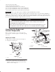
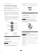
Figure 26
1. Traction rod 2. Jam nut
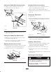
6. Start the traction unit and set the throttle to about 1/3
open position.
When the traction unit is running, you could be
caught and injured in moving parts or burned on
hot surfaces.
Stay away from pinch points, moving parts, and
hot surfaces when adjusting the running traction
unit.
Warning
7. If the left track moves, lengthen or shorten the right
traction rod until the track stops moving.
8. If the right track moves, lengthen or shorten the left
traction rod until the track stops moving.
9. Tighten the jam nuts.
10. Close the rear access cover.
11. Stop the engine and lower the traction unit to the
ground.
Adjusting the Tracking of the Traction
Control, Full Forward Position
If the traction unit does not drive straight when you hold
the traction control against the reference bar, complete the
following procedure:
1. Drive the traction unit with the traction control against
the reference bar, noting which direction the traction
unit veers.
2. Release the traction control.
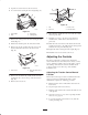
3. If the traction unit veers to the left, loosen the the
right jam nut and adjust the tracking set screw on the
front of the traction control (Fig. 27).
4. If the traction unit veers to the right, loosen the the
left jam nut and adjust the tracking set screw on the
front of the traction control (Fig. 27).
m–4664
1
1
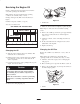
Figure 27
1. Jam nut and set screw
5. Repeat steps 1 through 4 until the traction unit drives
straight in the full forward position.
Adjusting the Auxiliary Hydraulics Lever,
Reverse Flow Stop
In the reverse flow slot of the auxiliary hydraulics lever
assembly is a bolt that keeps the lever from going too far
into the slot into a detent position (i.e., a position that
allows it to stay in the slot without being held by the
operator). If the lever goes into a detent position, or if the
reverse flow hydraulics speed is slow, adjust the bolt using
the following procedure:
1. Stop the engine and remove the key.
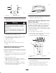
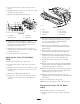
2. Remove the three bolts securing the left control panel
cover and remove the cover (Fig. 28).
3. Loosen the jam nut on the adjustment bolt (Fig. 28).
m–4777
2
3
1
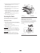
Figure 28
1. Left control panel cover
2. Jam nut
3. Adjustment bolt
4. Turn the adjustment bolt clockwise until the lever slips
into a detent position.
5. Slowly turn the adjustment bolt counter-clockwise
until the lever slips out of a detent position.
6. Hold the adjustment bolt and tighten the jam nut.