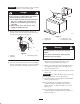
Form No. 3326-500 TX 425 Dingo Compact Utility Loader Model No.
Warning Checking the Hydraulic Fluid . . . . . . . . . . . . . . . Operation . . . . . . . . . . . . . . . . . . . . . . . . . . . . . . . . . . Traction Unit Overview . . . . . . . . . . . . . . . . . . . . Controls . . . . . . . . . . . . . . . . . . . . . . . . . . . . . . . . Starting and Stopping the Engine . . . . . . . . . . . . Stopping the Traction Unit . . . . . . . . . . . . . . . . . Moving a Non-functioning Traction Unit . . . . . . Using the Cylinder Lock . . . . . . . . . . . . . . . . . . .
Read this manual carefully to learn how to operate and maintain your product correctly. Reading this manual will help you and others avoid personal injury and damage to the product. Although we design, produce and market safe, state-of-the-art products, you are responsible for using the product properly and safely. You are also responsible for training persons, who you allow to use the product, about safe operation.
• Slow down and use extra care on hillsides. Be sure to travel in the recommended direction on hillsides. Turf conditions can affect the machine’s stability. • Do not touch parts which may be hot from operation. Allow them to cool before attempting to maintain, adjust, or service. • Slow down and use caution when making turns and when changing directions on slopes. • Check for overhead clearances (i.e. branches, doorways, electrical wires) before driving under any objects and do not contact them.
• Do not operate near drop-offs, ditches, or embankments. The traction unit could suddenly turn over if a track goes over the edge of a cliff or ditch, or if an edge caves in. • Keep the traction unit free of grass, leaves, or other debris build-up. Clean up oil or fuel spillage. Allow the traction unit to cool before storing. • Use extra care when handling gasoline and other fuels. They are flammable and vapors are explosive. • Do not operate on wet grass. Reduced traction could cause sliding.
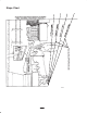
Slope Chart M 4402 6
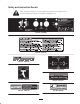
Safety and Instruction Decals Safety decals and instructions are easily visible to the operator and are located near any area of potential danger. Replace any decal that is damaged or lost. Part No. 104-2842 Part No. 100-6140 Part No. 100-6132 Part No. 100-6138 Part No. 100-6136 Part No. 100-6141 Part No. 100-6135 Part No.
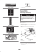
Part No. 93-9084 Part No. 100-6101 1. Tie-down /lift point Assembly Activating the Battery Warning Part No. 104-2837 Battery posts, terminals, and related accessories contain lead and lead compounds, chemicals known to the State of California to cause cancer and reproductive harm. Wash hands after handling. The traction unit is shipped with a dry battery. Purchase bulk electrolyte with 1.260 specific gravity from a local battery supply outlet. 1.
Important Do not allow the battery posts to touch the frame or hydraulic lines or it may cause sparks. 4 Danger 2 3 Battery electrolyte contains sulfuric acid which is a deadly poison and causes severe burns. 1 • Do not drink electrolyte and avoid contact with skin, eyes or clothing. Wear safety glasses to shield your eyes and rubber gloves to protect your hands. • Fill the battery where clean water is always available for flushing the skin. 4. Remove filler caps from the battery.
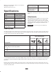
Note: Ensure that the battery cables do not contact any sharp edges or each other. 12. Close the rear access cover. Specifications Width 41 inches (104 cm) Length 71 inches (180 cm) Height 43 inches (109 cm) Weight 2007 lbs (910 Kg) Operating capacity 500 lbs (227 Kg) Tipping capacity 1480 lbs (671 Kg) Wheelbase 31.
Before Operating Important Do not use methanol, gasoline containing methanol, or gasohol containing more than 10% ethanol because the fuel system could be damaged. Do not mix oil with gasoline. Before operating, check the fuel and oil level, and remove debris from the traction unit. Also, ensure that the area is clear of people and debris. You should also know and have marked the locations of all utility lines.
6. Clean any debris build-up on the engine and in the oil cooler fins with a brush or blower. 2 Important It is preferable to blow dirt out, rather than washing it out. If water is used, keep it away from electrical items and hydraulic valves. Do not use a high-pressure washer. High-pressure washing can damage the electrical system and hydraulic valves or deplete grease. 1 m-5232 m–3219 7. Clean debris from the cooler fan grill on the hood. Figure 4 1. Oil dipstick 8. Close the hood. 2.
Operation Traction Unit Overview Figure 7 contains a front and back view of the traction unit. Familiarize yourself with all of the traction unit components listed in Figure 7. 6 5 11 10 7 4 8 3 14 2 m–4732 1 m 5241 9 12 13 Figure 7 1. 2. 3. 4. Track Track adjustment chamber Lift cylinder Cylinder lock 5. 6. 7. 8. Loader arms Hood Auxiliary hydraulic couplers Tilt cylinder 9. Mount plate 10. Tie-down/lift loop 11. Control panel 12. Rear access cover 13. Fuel tank 14.
Key Switch The key switch, used to start and stop the engine, has three positions: off, run, and start. To start the engine, rotate the key to the start position. Release the key when engine starts and it will move automatically to the run position. To stop the engine, rotate the key to the off position. m–4664 Throttle Lever Figure 9 Move the control forward to increase the engine speed and rearward to decrease speed.
Loader Valve Lock 1 The loader valve lock secures the loader arm/attachment tilt lever so that you cannot push it forward. This helps to ensure that no one will accidentally lower the loader arms during maintenance. Secure the loader arms with the lock anytime you need to stop the machine with the loader arms raised. m–4665 Figure 12 1. Neutral 2. Forward flow hydraulics 3.
Stopping the Engine After 50 hours and then every 100 hours thereafter (that is at 150, 250, 350, etc.) the screen displays CHG OIL to remind you to change the engine oil. After every 100 hours, the screen displays SVC to remind you to perform the other maintenance procedures based on a 100, 200, or 400 hour schedule. These reminders come on starting three hours prior to the service interval time and flash at regular intervals for six hours. 1. Move the throttle lever to the slow (turtle) position. 2.
1 2 3 4 1 m–4672 2 Figure 15 1. Cylinder lock 2. Lift cylinder m–4767 3. Clevis pin 4. Hairpin cotter Figure 14 1. Left tow valve (right track) 7. Slowly lower the loader arms until cylinder lock contacts the cylinder body and rod end. 2. Right tow valve (left track) 4. Tow the traction unit as required. Removing/Storing the Cylinder Lock 5. When the traction unit has been repaired, close the tow valves before operating it.
Important Before installing the attachment, ensure that the mount plates are free of any dirt or debris and that the pins rotate freely. If the pins do not rotate freely, grease them; refer to Greasing the Traction Unit, page 29. 2 1. Position the attachment on a level surface with enough space behind it to accommodate the traction unit. 2. Start the engine. 3. Tilt the attachment mount plate forward. 4. Position mount plate into the upper lip of the attachment receiver plate (Fig. 16).
8. Confirm that the connection is secure by pulling on the hoses. 1. Stop the engine. 2. Move the auxiliary hydraulics lever forward, backward, and back to neutral to relieve pressure at the hydraulic couplers. 9. Move the auxiliary hydraulics lever to neutral. Removing an Attachment 3. Move the auxiliary hydraulics lever into the detent position. 1. Lower the attachment to the ground 4. Remove the protective covers from the hydraulic couplers on the traction unit. 2. Stop the engine. 5.
Maintenance Recommended Maintenance Schedule Maintenance Service Interval Maintenance Procedure 8 hours • • • • 25 hours • Clean the foam pre-filter and the paper air filter1 • Check hydraulic oil level6 • Inspect hydraulic lines for leaks 100 hours • • • • • Change engine oil1, 2 Check battery electrolyte level Replace the paper air filter1 Adjust the track tension Check battery cable connections 200 hours • • • • Change engine oil filter (every other oil change)1, 4 Change hydraulic filter1, 3,
Caution If you leave the key in the ignition switch, someone could accidently start the engine and seriously injure you or other bystanders. Remove the key from the ignition and disconnect the wire from the spark plug before you do any maintenance. Set the wire aside so that it does not accidentally contact the spark plug. Accessing the Engine and Internal Components Before opening any of the covers, stop the engine and remove the key. Allow the engine to cool before opening any covers Opening the Hood 1.
Removing the Front Screen 2. Place the latch over the locking bracket (Fig. 20). 3. Pull the latch rearward and push it in to lock it in place (Fig. 20). Caution Removing a Side Screen If the engine has been running the heat shield will be very hot and could burn you. 1. Open the hood. Allow the traction unit cool completely before touching the heat shield. 2. Pull out and turn the two locking tabs on the inside of the side screen until they line up with the slots in the screen (Fig. 21). 1.
Adjusting the Controls 1 The factory adjusts the controls before shipping the traction unit. However, after many hours of use, you may need to adjust the neutral position of the traction control, the tracking of the traction control in the full forward position, and the reverse flow stop of the auxiliary hydraulics lever.
8. If the right track moves, lengthen or shorten the left traction rod until the track stops moving. 2. Remove the three bolts securing the left control panel cover and remove the cover (Fig. 27). 9. Tighten the jam nuts. 3. Loosen the jam nut on the adjustment bolt (Fig. 27). 10. Close the rear access cover. 11. Stop the engine and lower the traction unit to the ground.
1 2 1 3 4 2 5 m–1213 6 7 Figure 30 1. Paper element 8 2. Rubber seal m–4653 Installing the Filters Figure 28 1. 2. 3. 4. Knob Air cleaner cover Cover nut Cover 5. 6. 7. 8. Foam pre-filter Paper filter Rubber seal Air cleaner base Important To prevent engine damage, always operate the engine with the complete foam and paper air cleaner assembly installed. 1. Carefully slide the foam pre-filter onto the paper filter (Fig. 28). 5.
Changing the Oil Changing the Oil Filter 1. Start the engine and let it run for five minutes. This warms the oil so it drains better. Replace the oil filter every 200 hours or every other oil change. 2. Park the traction unit so that the drain side is slightly lower than the opposite side to ensure that the oil drains completely. Note: Change the oil filter more frequently when operating conditions are extremely hot, dusty, or sandy. 1. Drain the oil from the engine; refer to Changing the Oil, page 26.
m–4775 Servicing the Tracks Check the tracks for excessive wear and clean them periodically. If the tracks are worn, replace them. 1 Cleaning the Tracks 1. With a bucket on the loader arms, lower the bucket to the ground so that the front of the traction unit lifts off of the ground a few inches. 2. Stop the engine, and remove the key. 3. Using a water hose or pressure washer, remove dirt from each track system. Important Ensure that you only use high-pressure water to wash the track area.
Servicing the Spark Plugs 1. Lower the loader arms, stop the engine, and remove the key. Check the spark plugs after every 200 operating hours. Ensure that the air gap between the center and side electrodes is correct before installing each spark plug. Use a spark plug wrench for removing and installing the spark plugs and a gapping tool/feeler gauge to check and adjust the air gap. Install new spark plugs if necessary. 2.
2 3 1 0.030 in. (0.76 mm) m–4056 Figure 40 4. Pump grease into the fittings until grease begins to ooze out of the bearings (approximately 3 pumps). m–3215 Figure 38 1. Center electrode insulator 2. Side electrode 5. Wipe up any excess grease. 3. Air gap (not to scale) Changing the Fuel Filter Change the fuel filter after every 200 operating hours or yearly, whichever occurs first. Installing the Spark Plugs 1. Thread the spark plugs into the spark plug holes. 1.
9. Remove the clamp blocking fuel flow and open the fuel valves. 7. Apply a thin coat hydraulic fluid to the rubber gasket on the replacement filter. 10. Secure the tank cap. 8. Install the replacement hydraulic filter onto the filter adapter (Fig. 42). Tighten it clockwise until the rubber gasket contacts the filter adapter, then tighten the filter an additional 3/4 turn. 11. Replace the side screen and close the hood.
2. Open the hood, refer to Opening the Hood, page 21. 3. Install the cylinder lock, stop the engine, and remove the key. 9. Fill the hydraulic tank with approximately 12 gal. (45.4 l) of 10W-30 detergent oil (API service SG, SH, SJ, or higher); refer to Checking Hydraulic Fluid, page 12. 4. Allow the traction unit to cool completely. 10. Start the engine and let it run for a few minutes. 5. Remove the hydraulic tank cap and dipstick (Fig. 43). 11. Stop the engine.
Checking the Electrolyte Level Warning 1. Open covers to see into the cells. The electrolyte must be up to the lower part of the tube (Fig. 45). Charging the battery produces gasses that can explode. Important Do not allow the electrolyte to get below the plates. (Fig. 45). Never smoke near the battery and keep sparks and flames away from battery. 1 Cleaning the Chassis 2 3 Over time, the chassis under the engine collects dirt and debris that must be removed.
19. On the right side of the tank, connect the orange wire to the center post and the black wire to the outside post (Fig. 47). 8. Loosen the tank cap to relieve pressure. 9. Place a clamp on the fuel line, two inches from where it comes out of the fuel tank. 20. Slide the tank all the way into the traction unit. 10. Slide the fuel tank to the rear (Fig. 46). Important The fuel line and wires must be away from the engine pulleys and the frame. 11. Disconnect the fuel line. 12.
11. For storage over 30 days, prepare the traction unit as follows. A. Add a petroleum based stabilizer/conditioner to fuel in the tank. Follow mixing instructions from stabilizer manufacturer. (1 oz. per gallon). Do not use an alcohol based stabilizer (ethanol or methanol). Note: A fuel stabilizer/conditioner is most effective when mixed with fresh gasoline and used at all times. B. Run the engine to distribute conditioned fuel through the fuel system (5 minutes). C.
Troubleshooting PROBLEM Starter does not crank POSSIBLE CAUSES CORRECTIVE ACTION 1. Battery is dead. 1. Charge the battery. 2. Electrical connections are corroded or loose. 2. Check electrical connections for good contact. 3. Relay or switch is defective. 3. Contact Authorized Service Dealer. 1. Fuel tank is empty. 1. Fill fuel tank with gasoline. 2. Choke is not on. 2. Move choke lever fully forward. 3. Air cleaner is dirty. 3. Clean or replace air cleaner element. 4.
The Toro Dingo Product Line Warranty A One-Year Limited Warranty Conditions and Products Covered The Toro Company and its affiliate, Toro Warranty Company, pursuant to an agreement between them, jointly warrant your Toro Dingo Product (“Product”) to be free from defects in materials or workmanship.