
Service Manual


HY13-1512-006-M1/USA
Torqmotor™ Service Procedure
TC, TS, TB, TE, TJ, TF, TG, TH and TL Series
Parker Hannifi n Corporation
Hydraulic Pump/Motor Division
Greeneville, TN 37745 US
31
Disassembly and Inspection
Place
Torqmotor
in a vise
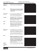
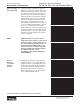
1. Place the Torqmotor™ in a soft jawed vice,
with coupling shaft (12) pointed down and
the vise jaws clamping fi rmly on the sides
of the housing (18) mounting fl ange or port
bosses. Remove manifold port O-Rings
(18A) if applicable.
WARNING
WARNING: IF THE TORQMOTOR™ IS NOT
FIRMLY HELD IN THE VISE, IT COULD BE
DISLODGED DURING THE SERVICE PRO-
CEDURES, CAUSING INJURY.
Scribe alignment
mark & loose
valve plugs
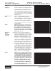
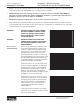
2. Scribe an alignment mark down and across
the Torqmotor™ components from end
cover (2) to housing (18) to facilitate reas-
sembly orientation where required. Loosen
two shuttle or relief valve plugs (21) for
disassembly later if included in end cover.
3/16 or 3/8 inch Allen wrench or 1 inch hex
socket required. SEE FIGURES 3 & 4.
Remove special
bolts &
inspect bolts
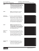
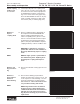
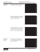
3. Remove the fi ve, six, or seven special
ring head bolts (1, 1A, 1B, or 1C) using an
appropriate 1/2 or 9/16 inch size socket.
SEE FIGURE 5. Inspect bolts for damaged
threads, or sealing rings, under the bolt
head. Replace damaged bolts. SEE FIGURE
6.
Reference Exploded Assembly View
Figure 6
Figure 5
Figure 4
Figure 3