
Service Manual


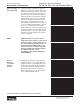


HY13-1512-006-M1/USA
Torqmotor™ Service Procedure
TC, TS, TB, TE, TJ, TF, TG, TH and TL Series
Parker Hannifi n Corporation
Hydraulic Pump/Motor Division
Greeneville, TN 37745 US
32
Remove end
cover &
inspect bolts
NOTE
Remove plugs
and valves
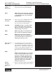
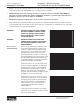
4. Remove end cover assembly (2) and seal
ring (4). Discard seal ring. SEE FIGURE 7.
NOTE: Refer to the appropriate “alternate
cover construction” on the exploded view
to determine the end cover construction
being serviced.
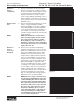
5. If the end cover (2) is equipped with shuttle
valve or relief valve (24) components,
remove the two previously loosened plugs
(21) and o-rings (22). SEE FIGURE 8.
CAUTION
NOTE
NOTE
CAUTION: Be ready to catch the shuttle
valve or relief valve components that
will fall out of the end cover valve cavity
when the plugs are removed.
NOTE: O-ring (22) is not included in seal
kits but serviced separately if required.
NOTE: The insert and if included the
orifi ce plug in the end cover (2) must not
be removed as they are serviced as an
integral part of the end cover.
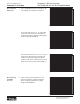
Wash & inspect
end cover
NOTE
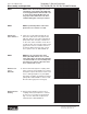
6. Thoroughly wash end cover (2) in proper
solvent and blow dry. Be sure the end cover
valve apertures, including the internal orifi ce
plug, are free of contamination. Inspect end
cover for cracks and the bolt head recesses
for good bolt head sealing surfaces. Re-
place end cover as necessary. SEE FIGURE
9.
NOTE: A polished pattern (not scratches)
on the cover from rotation of the commu-
tator (5) is normal. Discoloration would
indicate excess fl uid temperature, ther-
mal shock, or excess speed and require
system investigation for cause and close
inspection of end cover, commutator,
manifold, and rotor set.
Remove
& inspect
commutator
ring
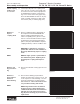
7. Remove commutator ring (6). SEE FIGURE 10.
Inspect commutator ring for cracks, or burrs.
Figure 10
Figure 9
Figure 8
Figure 7
Disassembly and Inspection