
Service Manual


HY13-1512-006-M1/USA
Torqmotor™ Service Procedure
TC, TS, TB, TE, TJ, TF, TG, TH and TL Series
Parker Hannifi n Corporation
Hydraulic Pump/Motor Division
Greeneville, TN 37745 US
33
Remove &
inspect
commutator
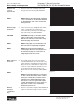
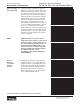
8. Remove commutator (5) and seal ring (3)
Remove seal ring from commutator, using
an air hose to blow air into ring groove until
seal ring is lifted out and discard seal ring.
Inspect commutator for cracks or burrs,
wear, scoring, spalling or brinelling. If any of
these conditions exist, replace commutator
and commutator ring as a matched set. SEE
FIGURE 11 & 12.
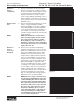
Remove mani-
fold
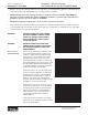
9. Remove manifold (7) and inspect for cracks
surface scoring, brinelling or spalling.
Replace manifold if any of these conditions
exist. SEE FIGURE 13. A polished pattern
on the ground surface from commutator or
rotor rotation is normal. Remove and dis-
card the seal rings (4) that are on both sides
of the manifold.
NOTE NOTE: The manifold is constructed of
plates bonded together to form an inte-
gral component not subject to further
disassembly for service. Compare con-
fi guration of both sides of the manifold to
ensure that same surface is reassembled
against the rotor set.
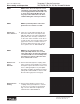
Remove &
inspect
rotor set &
wearplate
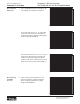
10. Remove rotor set (8) and wearplate (9),
together to retain the rotor set in its assem-
bled form, maintaining the same rotor vane
(8C) to stator (8B) contact surfaces. SEE
FIGURE 14. The drive link (10) may come
away from the coupling shaft (12) with the
rotor set, and wearplate. You may have to
shift the rotor set on the wearplate to work
the drive link out of the rotor (8A) and wear-
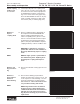
plate. SEE FIGURE 15. Inspect the rotor
set in its assembled form for nicks, scoring,
or spalling on any surface and for broken
or worn splines. If the rotor set component
requires replacement, the complete rotor
set must be replaced as it is a matched set.
Inspect the wearplate for cracks, brinel-
ling, or scoring. Discard seal ring (4) that is
between the rotor set and wearplate.
NOTE NOTE: The rotor set (8) components may
become disassembled during service pro-
cedures. Marking the surface of the rotor
and stator that is facing UP, with etching
ink or grease pencil before removal from
Torqmotor™ will ensure correct reassem-
bly of rotor into stator and rotor set into
Torqmotor™. Marking all rotor compo-
nents and mating spline components for
exact repositioning at assembly will en-
sure maximum wear life and performance
of rotor set and Torqmotor™.
Figure 11
Figure 12
Figure 13
Figure 14
Disassembly and Inspection