
Service Manual


HY13-1512-006-M1/USA
Torqmotor™ Service Procedure
TC, TS, TB, TE, TJ, TF, TG, TH and TL Series
Parker Hannifi n Corporation
Hydraulic Pump/Motor Division
Greeneville, TN 37745 US
35
Check coupling
shaft for rust
or corrosion
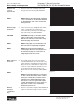
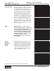
14. Check exposed portion of coupling shaft
(12) to be sure you have removed all signs
of rust and corrosion which might prevent
its withdrawal through the seal and bear-
ing. Crocus cloth or fi ne emery paper may
be used. SEE FIGURE 19. Remove any key
(12A), nut (12B), washer (12C), bolt (12D),
lock washer (12E), or retaining ring (12F).
Remove &
inspect
coupling shaft
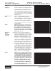
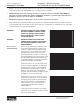
15. Remove coupling shaft (12), by pushing on
the output end of shaft. SEE FIGURE 20.
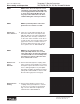
Inspect coupling shaft bearing and seal
surfaces for spalling, nicks, grooves, severe
wear or corrosion and discoloration. Inspect
for damaged or worn internal and external
splines or keyway. SEE FIGURE 21. Replace
coupling shaft if any of these conditions exist.
NOTE
NOTE
NOTE: Minor shaft wear in seal area is
permissible. If wear exceeds .020 inches
(0.51 mm) diametrically, replace coupling
shaft.
NOTE: A slight “polish” is permissible in
the shaft bearing areas. Anything more
would require coupling shaft replace-
ment.
Remove seal
ring from hous-
ing
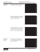
16. Remove and discard seal ring (4) from hous-
ing (18).
Remove &
inspect thrust
washer &
thrust bearing
NOTE
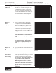
17. Remove thrust bearing (15) and thrust
washer (14) if the unit is a Series TC, TS, TB
or TE. Inspect for wear, brinelling, corrosion
and a full complement of retained rollers.
SEE FIGURE 22. Note: The TL motor has
only one thrust bearing and washer.
NOTE: Large Frame Series TF, TG & TJ
Torqmotors have a thrust bearing (15)
sandwiched between two thrust washers
(14) that cannot be removed from hous-
ing (18) unless bearing (13) is removed for
replacement.
Figure 22
Figure 21
Figure 20
Figure 19
Disassembly and Inspection
Inspection Areas