
Service Manual


HY13-1512-006-M1/USA
Torqmotor™ Service Procedure
TC, TS, TB, TE, TJ, TF, TG, TH and TL Series
Parker Hannifi n Corporation
Hydraulic Pump/Motor Division
Greeneville, TN 37745 US
42
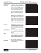
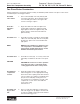
Install
coupling
shaft
8. Be sure that a generous amount of clean
corrosion resistant grease has been applied
to the lower (outer) housing bearing/bushing
(19). Install the coupling shaft (12) into hous-
ing (18), seating it against the thrust bearing
(15) in TC, TS, TB and TE Series housings
and against the second thrust washer (14)
in TF, TL, TG and TH Series housings. SEE
FIGURE 47.
CAUTION
NOTE
CAUTION: The outer bearing (19) is not
lubricated by the system’s hydraulic
fl uid. Be sure it is thoroughly packed with
the recommended grease, Parker Gear
grease specifi cation #045236, E/M Lubri-
cant #K-70M.
NOTE: Mobil Mobilith SHC ® 460
NOTE: A 102 Tube (P/N 406010) is includ-
ed in each seal kit.
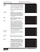
NOTE NOTE: The coupling shaft (12) will be
fl ush or just below the housing wear
surface on Small Frame, Series TC, TS,
TB, TE & TJ Torqmotors™ when properly
seated while the coupling shaft (12) on
Large Frame, Series TF, TL, TG, or TH
Torqmotors™ will be approximately .10
inch (2.54 mm) below the housing wear
plate surface to allow the assembly of
thrust bearing (11). The coupling shaft
must rotate smoothly on the thrust bear-
ing package. SEE FIGURE 48.
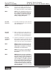
Install thrust
bearing
9. Install thrust bearing (11) onto the end of
coupling shaft (12) only if you are servicing
an TF, TL, TG, TH or TL Series Torqmotor™.
SEE FIGURE 49.
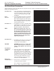
Insert seal
ring
10. Apply a small amount of clean grease to a
new seal ring (4) and insert it into the hous-
ing (18) seal ring groove. SEE FIGURE 50.
NOTE NOTE: One or two alignment studs
screwed fi nger tight into housing (18) bolt
holes, approximately 180 degrees apart,
will facilitate the assembly and alignment
of components as required in the follow-
ing procedures. The studs can be made
by cutting off the heads of either
3/8-24 UNF 2A or 5/16-24 UNF 2A bolts
as required that are over .5 inch (12.7
mm) longer than the bolts (1, 1A, 1B, or
1C) used in the Torqmotor™.
Figure 47
Figure 48
Figure 49
Figure 50
Torqmotor™ Assembly