
Service Manual


HY13-1512-006-M1/USA
Torqmotor™ Service Procedure
TC, TS, TB, TE, TJ, TF, TG, TH and TL Series
Parker Hannifi n Corporation
Hydraulic Pump/Motor Division
Greeneville, TN 37745 US
43
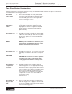
Install
drive link
NOTE
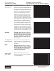
11. Install drive link (10) the long splined end
down into the coupling shaft (12) and en-
gage the drive link splines into mesh with
the coupling shaft splines. SEE FIGURE 51.
NOTE: Use any alignment marks put on
the coupling shaft and drive link before
disassembly to assemble the drive link
splines in their original position in the
mating coupling shaft splines.
Assemble
wear plate
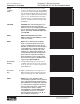
12. Assemble wear plate (9) over the drive link
(10) and alignment studs onto the housing
(18). SEE FIGURE 52.
Assemble
seal ring
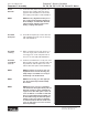
13. Apply a small amount of clean grease to a
new seal ring (4) and assemble it into the
seal ring groove on the wear plate side of
the rotor set stator (8B). SEE FIGURE 53.
Install the
assembled
rotor set
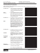
14. Install the assembled rotor set (8) onto wear
plate (9) with rotor (8A) counterbore and seal
ring side down and the splines into mesh
with the drive link splines. SEE FIGURE 54.
NOTE NOTE: It may be necessary to turn one
alignment stud out of the housing (18)
temporarily to assemble rotor set (8) or
manifold (7) over the drive link.
NOTE NOTE: If necessary, go to the appropri-
ate, “Rotor Set Component Assembly
Procedure.”
NOTE NOTE: The rotor set rotor counterbore
side must be down against wear plate for
drive link clearance and to maintain the
original rotor-drive link spline contact. A
rotor set without a counterbore and that
was not etched before disassembly can
be reinstalled using the drive link spline
pattern on the rotor splines if apparent,
to determine which side was down. The
rotor set seal ring groove faces toward
the wear plate (9).
Figure 51
Figure 52
Figure 53
Figure 54
Torqmotor™ Assembly