
Service Manual


HY13-1512-006-M1/USA
Torqmotor™ Service Procedure
TC, TS, TB, TE, TJ, TF, TG, TH and TL Series
Parker Hannifi n Corporation
Hydraulic Pump/Motor Division
Greeneville, TN 37745 US
46
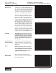
Assemble seal
ring &
end cover
22. Assemble a new seal ring (4) into end cover
(2) and assemble end cover over the align-
ment studs and onto the commutator set.
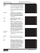
SEE FIGURE 63, 64. If the end cover has
only 5 bolt holes be sure the cover holes are
aligned with the 5 threaded holes in hous-
ing (18). The correct 5 bolt end cover bolt
hole relationship to housing port bosses is
shown in FIGURE 65.
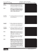
NOTE NOTE: If the end cover has a valve (24)
or has fi ve bolt holes, use the line you
previously scribed on the cover to radi-
ally align the end cover into its original
position.
Assemble
cover bolts
23. Assemble the 5, 6 or 7 special bolts (1, 1A,
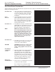
1B or 1C) and screw in fi nger tight. Remove
and replace the two alignment studs with
bolts after the other bolts are in place. Al-
ternately and progressively tighten the bolts
to pull the end cover and other components
into place with a fi nal torque of 25-30 ft. lbs.
(34-41 N m) for the fi ve TC, TS, TB or six TE
Series 5/16 24 threaded bolts or six TJ bolts
or 50-55 ft. lbs. (68-75 N m) for the seven
TF, TL, TG & TH Series 3/8-24 threaded
bolts. SEE FIGURE 66, 67, 68.
Figure 63
Figure 64
Figure 65
Figure 66
Torqmotor™ Assembly