Form No. 3350-119 Rev A Dingo TX 420 and TX 425 Compact Utility Loader Model No. 22306—240000301 and Up Model No. 22307—240000301 and Up Operator’s Manual Register your product at www.Toro.
Warning Checking the Oil Level . . . . . . . . . . . . . . . . . . . . Removing Debris from the Traction Unit . . . . . . Checking the Hydraulic Fluid . . . . . . . . . . . . . . . Operation . . . . . . . . . . . . . . . . . . . . . . . . . . . . . . . . . . Traction Unit Overview . . . . . . . . . . . . . . . . . . . . Controls . . . . . . . . . . . . . . . . . . . . . . . . . . . . . . . . Starting and Stopping the Engine . . . . . . . . . . . . Stopping the Traction Unit . . . . . . . . . . . . . . . .
or Service Representative provide exact information about your specific product. The two numbers are stamped into a plate mounted under the hood near the belt drive. Warning Engine exhaust contains carbon monoxide, an odorless, deadly poison that can kill you. For your convenience, write the product model and serial numbers in the space below. Do not run the engine indoors or in an enclosed area. Model No: Serial No. Training • Read the Operator’s Manual and other training material.
• Do not over-load the attachment and always keep the load level when raising the loader arms. Logs, boards, and other items could roll down the loader arms, injuring you. Operation • Never run an engine in an enclosed area. • Only operate in good light, keeping away from holes and hidden hazards. • Never jerk the controls; use a steady motion. • Be sure all drives are in neutral and parking brake is engaged before starting the engine. Only start the engine from the operator’s position.
• If any maintenance or repair requires the loader arms to be in the raised position, secure the arms in the raised position with the hydraulic cylinder lock. • Keep all movements on slopes slow and gradual. Do not make sudden changes in speed or direction. • Avoid starting or stopping on a slope. If the traction unit loses traction, proceed slowly, straight down the slope. • Secure the loader arm valve with the loader valve lock anytime you need to stop the machine with the loader arms raised.
Slope Chart M 4402 6
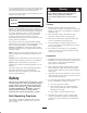
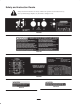
Safety and Instruction Decals Safety decals and instructions are easily visible to the operator and are located near any area of potential danger. Replace any decal that is damaged or lost.
100-6135 104-2837 100-6141 100-6136 104-2838 100-6138 104-2844 80-8040 93-9084 1. Lift point 105-8432 80-8290 9 2.
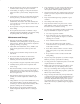
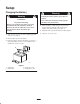
Setup Charging the Battery Warning Warning Charging the battery produces gasses that can explode. CALIFORNIA Never smoke near the battery and keep sparks and flames away from battery. Proposition 65 Warning Battery posts, terminals, and related accessories contain lead and lead compounds, chemicals known to the State of California to cause cancer and reproductive harm. Wash hands after handling. 4.
Attachments Specifications Many attachments are available for use with the traction unit. These attachments allow you to to perform many different functions with the traction unit such as hauling materials, digging holes, grading, and more. Contact your Toro dealer for a list of all approved attachments and accessories. Specifications and design are subject to change without notice.
Stability Data The following tables list the maximum slope recommended for the traction unit in the positions listed in the tables. Slopes over the listed degree may cause the traction unit to become unstable. The data in the tables assume that the loader arms are fully lowered; raised arms may affect the stability. In each attachment manual is a set of three stability ratings, one for each hill position.
Before Operating Important Do not use methanol, gasoline containing methanol, or gasohol containing more than 10% ethanol because the fuel system could be damaged. Do not mix oil with gasoline. Before operating, check the fuel and oil level, and remove debris from the traction unit. Also, ensure that the area is clear of people and debris. You should also know and have marked the locations of all utility lines.
6. Clean any debris build-up on the engine and in the oil cooler fins with a brush or blower. 2 Important It is preferable to blow dirt out, rather than washing it out. If water is used, keep it away from electrical items and hydraulic valves. Do not use a high-pressure washer. High-pressure washing can damage the electrical system and hydraulic valves or deplete grease. 1 m-5232 m–3219 7. Clean debris from the cooler fan grill on the hood. Figure 2 1. Oil dipstick 8. Close the hood. 2.
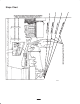
Operation Traction Unit Overview Figure 5 contains a front and back view of the traction unit. Familiarize yourself with all of the traction unit components listed in Figure 5. 6 5 11 10 7 4 8 3 14 2 m-4732 1 m-5241 9 13 12 Figure 5 1. 2. 3. 4. Track Track adjustment chamber Lift cylinder Cylinder lock 5. 6. 7. 8. Loader arms Hood Auxiliary hydraulic couplers Tilt cylinder 9. Mount plate 10. Tie-down/lift loop 11. Control panel 12. Rear access cover 13. Fuel tank 14.
Key Switch Loader Arm/Attachment Tilt Lever The key switch, used to start and stop the engine, has three positions: off, run, and start. To tilt the attachment forward, slowly move the lever to the right (Fig. 8). To start the engine, rotate the key to the start position. Release the key when engine starts and it will move automatically to the run position. To tilt the attachment rearward, slowly move the lever to the left (Fig. 8). To stop the engine, rotate the key to the off position.
2 2 1 m–5918 m-5238 Figure 11 Figure 9 1. Loader valve lock 2. Loader arm/attachment tilt lever To release the brake, pull the lever rearward and right, out of the notch, and then push it forward. Auxiliary Hydraulics Lever Fuel Gauge To operate a hydraulic attachment in the forward direction, rotate the auxiliary hydraulics lever rearward and pull it down to the reference bar (Fig. 10, number 2). This gauge measures the amount of fuel in the fuel tank.
Moving a Non-functioning Traction Unit 4. Turn the ignition key to the start position. When the engines starts, release the key. Important Do not engage the starter for more than 10 seconds at a time. If the engine fails to start, allow a 30 second cool-down period between attempts. Failure to follow these instructions can burn out the starter motor. Important Do not tow or pull the traction unit without first opening the tow valves, or the hydraulic system will be damaged 5.
Connecting an Attachment 5. Lower the cylinder lock over the cylinder rod and secure it with the clevis pin and hairpin cotter (Fig. 13). Important Use only Toro-approved attachments. Attachments can change the stability and the operating characteristics of the traction unit. The warranty of the traction unit may be voided if used with unapproved attachments. 1 3 4 2 Important Before installing the attachment, ensure that the mount plates are free of any dirt or debris and that the pins rotate freely.
Note: When you connect the attachment male connector first, you will relieve any pressure build up in the attachment. Warning If you do not fully seat the quick attach pins through the attachment mount plate, the attachment could fall off of the traction unit, crushing you or bystanders. Warning Hydraulic fluid escaping under pressure can penetrate skin and cause injury.
Securing the Traction Unit for Transport Important roadways. 3. Set the parking brake. 4. Secure the traction unit to the trailer with chains or straps using the tie-down/lift loops (Fig. 5) to secure the rear of the traction unit and the loader arms/mount plate to secure the front of the traction unit. Do not operate or drive the traction unit on Important When transporting the traction unit on a trailer, always use the following procedure: Lifting the Traction Unit 1. Lower the loader arms.
5For severe duty or rental applications, change every 200 operating hours. the hydraulic fluid level before using the traction unit for the first time 6Check Important Refer to your engine operator’s manual for additional maintenance procedures. Note: After 50 hours and then every 100 hours thereafter (that is at 150, 250, 350, etc.) the screen displays CHG OIL to remind you to change the engine oil.
Removing the Front Screen 2. Swing the rear access cover to the right (Fig. 18). Caution If the engine has been running the heat shield will be very hot and could burn you. Allow the traction unit cool completely before touching the heat shield. m–4670 1. Open the hood and remove both side screens. Figure 18 2. Loosen the bolts securing the front weight (Fig. 20). Closing the Rear Access Cover 3 1 4 1. Swing the rear access cover to the left and seat it in place over the back of the traction unit.
6. Remove the shoulder bolts and nuts securing the oil cooler to the top of the front screen (Fig. 22). 5. Loosen the jam nuts on the traction rods, under the control panel (Fig. 23). 7. Remove the front screen. 1 4 4 1 2 2 1 2 m–4770 3 Figure 23 m–5921 1. Traction rod 2. Jam nut Figure 22 1. Nut 2. Oil cooler 6. Start the traction unit and set the throttle to about 1/3 open position. 3. Front screen 4. Shoulder bolts Warning 8.
5. Slowly turn the adjustment bolt counter-clockwise until the lever slips out of a detent position. 4. If the traction unit veers to the right, loosen the the left jam nut and adjust the tracking set screw on the front of the traction control (Fig. 24). 6. Hold the adjustment bolt and tighten the jam nut. m–4664 7. Install the left panel cover. Servicing the Air Cleaner 1 Foam Pre-filter: Clean every 25 operating hours. 1 Paper Filter: Clean every 25 operating hours.
1. Wash the foam pre-filter in liquid soap and warm water. When clean, rinse it thoroughly. 5. Close the hood. 2. Dry the pre-filter by squeezing it in a clean cloth (do not wring). Servicing the Engine Oil 3. Put one or two ounces of oil on the pre-filter (Fig. 27). Change oil after the first 50 operating hours and then every 100 operating hours thereafter. 2 Note: Change oil more frequently when operating conditions are extremely dusty or sandy.
4. Pour new oil of the proper type through the center hole of the filter. Stop pouring when the oil reaches the bottom of the threads. 1 5. Allow a minute or two for the oil to be absorbed by filter material, then pour off the excess oil. 6. Apply a thin coat of new oil to the rubber gasket on the replacement filter. m–4751 7. Install the replacement oil filter to the filter adapter.
1. Lower the loader arms, stop the engine, and remove the key. 2. Lift/support the side of the unit to be worked on so that the track is off of the ground. 1 3. Remove the locking bolt and nut (Fig. 33). 2 4 3 4 3 2 1 m–4736 Figure 31 1. Track 2. Tension wheel 3. Road wheels 4. Drive Sprocket m–4747 Figure 33 Adjusting the Track Tension 1. Locking bolt 2. Tensioning screw Check and adjust the track tension every 100 operating hours.
1 2. Lift/support the side of the unit to be worked on so that the track is 3 to 4 inches (7.6 to 10 cm) off of the ground. 3 4 3. Remove the locking bolt and nut (Fig. 33). 8 4. Using a 1/2 inch drive socket, release the drive tension by turning the tensioning screw clockwise (Fig. 33 and 35). 5 4 7 6 m–6782 10 5 1 3 2 9 Figure 34 1. 2. 3. 4. Track 1/2 inch socket Tension wheel Fork tube 5. 6. 7. 8. Track lug Drive sprocket Sprocket spacer Road wheels 6 8 7 5.
15. Install the outer tension wheel and secure it with the nut removed previously (Fig. 35). 1 16. Torque the nut to 300 ft-lb (407 N⋅m). 2 17. Turn the tensioning screw counter-clockwise until the distance between the tension nut and the back of the tension tube (Fig. 32) is 2-3/4 inches (7 cm). 4 3 5 18. Align the closest notch in the tension screw to the locking bolt hole and secure the screw with the locking bolt and nut. 6 19. Repeat steps 2 through 18 to replace the other track. m–6776 20.
Removing the Spark Plugs Installing the Spark Plugs 1. Lower the loader arms, stop the engine, and remove the key. 1. Thread the spark plugs into the spark plug holes. 2. Tighten the spark plugs to 20 ft-lb (27 N.m). 2. Open the hood; refer to Opening the Hood, page 22. 3. Push the wires onto the spark plugs (Fig. 38). 3. Pull the wires off of the spark plugs (Fig. 38). 4. Close the hood. 4. Clean around the spark plugs. Greasing the Traction Unit 5. Remove both spark plugs and metal washers.
Draining the Fuel Tank 1. Lower the loader arms, stop the engine, and remove the key. 2. Open the hood and remove the left side screen; refer to Accessing the Engine and Internal Components, page 22. Danger In certain conditions, gasoline is extremely flammable and highly explosive. A fire or explosion from gasoline can burn you and others and can damage property. 3. Loosen the tank cap to relieve pressure. 4. Clamp the fuel lines on both sides of the fuel filter (Fig. 42).
Note: The filler cap is behind the front screen. If you want to improve your access to it, remove the screen; refer to Removing the Front Screen, page 23. 1 m–5920 1 2 Figure 43 1. Hydraulic filter m–5377 9. Clean up any spilled fluid. Figure 44 10. Start the engine and let it run for about two minutes to purge air from the system. 1. Filler neck cap 2. Dipstick 11. Stop the engine and check for leaks. 6.
12. Check the hydraulic fluid level and top it off if necessary; refer to Checking Hydraulic Fluid, page 14. Checking the Electrolyte Level 13. Close the hood. 1. Open covers to see into the cells. The electrolyte must be up to the lower part of the tube (Fig. 46). Checking Hydraulic Lines Important Do not allow the electrolyte to get below the plates. (Fig. 46).
3. Install the filler caps after the battery is fully charged. 7. Remove the six nuts and bolts securing the rear panel, removing the panel (Fig. 47). Warning 8. Loosen the tank cap to relieve pressure. 9. Place a clamp on the fuel line, 2 inches from where it comes out of the fuel tank. Charging the battery produces gasses that can explode. 10. Slide the fuel tank to the rear (Fig. 47). Never smoke near the battery and keep sparks and flames away from battery. 11. Disconnect the fuel line. 12.
19. On the right side of the tank, connect the orange wire to the center post and the black wire to the outside post (Fig. 48). A. Add a petroleum based stabilizer/conditioner to fuel in the tank. Follow mixing instructions from stabilizer manufacturer. (1 oz. per US gallon). Do not use an alcohol based stabilizer (ethanol or methanol). 20. Slide the tank all the way into the traction unit. Important The fuel line and wires must be away from the engine pulleys and the frame.
Troubleshooting PROBLEM Starter does not crank POSSIBLE CAUSES CORRECTIVE ACTION 1. Battery is dead. 1. Charge the battery. 2. Electrical connections are corroded or loose. 2. Check electrical connections for good contact. 3. Relay or switch is defective. 3. Contact Authorized Service Dealer. 1. Fuel tank is empty. 1. Fill fuel tank with gasoline. 2. Choke is not on. 2. Move choke lever fully forward. 3. Air cleaner is dirty. 3. Clean or replace air cleaner element. 4.
Schematics Electrical Schematic 38
Hydraulic Schematic 39
The Toro Dingo Product Line Warranty A One-Year Limited Warranty Conditions and Products Covered The Toro Company and its affiliate, Toro Warranty Company, pursuant to an agreement between them, jointly warrant your Toro Dingo Product (“Product”) to be free from defects in materials or workmanship.