
Service Manual


32 PC Series
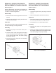
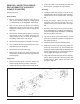
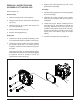
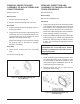
Refer to Figure 14.
Disassembly
1. Remove the retaining ring (22).
2. Remove the lip seal (20).
3. Remove the spacer (21).
3. Remove the shaft (18) and bearing (19) assembly
(18) from the pump.
Inspection
1. Inspect the input shaft (18) for worn splines,
surface damage, or keyway damage. Replace
shaft assembly if necessary.
2. Inspect the bearing (19) for evidence of scoring,
corrosion, or damage. If the bearing must be
replaced, remove the retaining ring (23) and use
a press or bearing puller to remove the bearing.
3. Inspect and replace the spacer (21) if it is bent
or broken.
4. Inspect and replace the retaining ring (22) if it is
bent or broken.
REMOVAL, INSPECTION AND
ASSEMBLY OF INPUT SHAFT
1. If removed, press bearing (19) onto shaft (18)
tight against the shoulder of the shaft. Install
retaining ring (23) onto the shaft (18).
2. Install input shaft assembly (18) into the housing
(1) bore. Light tapping with a rubber mallet may
be necessary on the input shaft (18) once the
bearing is aligned with the housing (1) bore.
Verify that the shaft rotates smoothly.
3. Install spacer (21).
4. Install new lip seal (20) with the flat side of the
seal toward the outside of the pump.
5. Remove the plastic wrap.
6. Install retaining ring (22).
Assembly
NOTE: During installation, lightly lubri-
cate all seals, O-rings and gaskets with
clean petroleum jelly prior to assembly.
Also, protect the inner diameter of seals
by covering the shaft with plastic wrap.
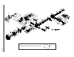
Figure 14. PC Pump Input Shaft
NOTE: Upon removal, all seals, O-rings
and gaskets should be replaced.
NOTE: If trunnion arm is to be removed,
do not assemble input shaft until the trun-
nion arm is installed.