
Service Manual


1P Series
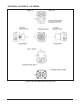
In some applications of the P Series Pumps, it is
desirable to move the machine for short distances at
low speeds without operating the engine. A screw-
type bypass valve is utilized in the pumps to permit
movement of the machine. The bypass valve is fully
opened when unscrewed two (2) turns maximum.
The bypass valve allows oil to be routed from one
side of the pump/motor circuit to the other, thus
allowing the motor to turn with minimal resistance.
An increase in resistance will occur with movement
at higher speeds. The bypass valve must be fully
closed during normal operation.
WARNING
Actuating the bypass will result in the
loss of hydrostatic braking capacity. The
machine must be stationary, on a level
surface and
in neutral when actuating the
bypass.
INTRODUCTION
The purpose of this manual is to provide informa-
tion useful in servicing the Hydro-Gear PC, PG,
PE PJ, PK, PR. PW and PY Pumps. This manual
includes the pump’s general descriptions, hydraulic
schematics, technical specications, servicing and
troubleshooting procedures for the pumps.
The P Series Pumps normally will not require
servicing during the life of the vehicle in which it
is installed. Should other servicing be required,
the exterior of the pump will need to be thoroughly
cleaned before beginning most procedures.
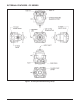
GENERAL DESCRIPTION
The P Series Pumps can be combined with wheel
motors and other remotely located units. These
pumps provide an innitely variable speed range
between zero and full displacement in both forward
and reverse modes of operation.
The P Series Pumps are of the axial piston design,
utilizing spherical nosed pistons. A compression
spring, located inside each piston, holds the nose
of the piston against a thrust bearing race.
The variable displacement pump features a cradle
swashplate with a direct-proportional displacement
control. Movement of the directional control shaft
produces a proportional swashplate movement and
a change in pump ow and/or direction.
Reversing the direction of the angle of the swash-
plate reverses the ow of oil from the pump and thus
reverses the direction of motor output rotation.
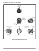
A fixed displacement gerotor charge pump is
provided in P Series Pumps. Oil from an external
reservoir and lter is pumped into the closed loop
by a charge pump. Fluid not required to replenish
the closed loop ows either into the pump housing
through a cooling orice, or back to the charge pump
inlet through the charge pressure relief valve.
Check or shock valves are included in the pump end
cap to control the makeup oil ow for the system.
The size and type of check valve can play an im-
portant role on the system pressure, response, and
amount of heat generated, due to the recirculation
of makeup oil ow. Shock valves are factory preset
pressure regulating check valves.
SECTION 1. DESCRIPTION AND OPERATION
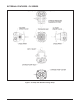
Additionally, some pumps may be equipped with
an Auxiliary Pump. The Auxiliary incorporates the
principles of the charge gerotor assembly and pro-
vides the capability of an external auxiliary ow for
an alternate hydraulic circuit to operate accessories
without loss of drive.