
Service Manual

63PJ Series
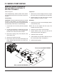
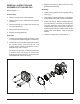
Refer to Figure 10.
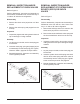
Disassembly
1. Prior to removal of the auxiliary pump, place a
mark on the auxiliary pump, charge pump (7)
and end cap (2) for alignment at assembly.
2. Use a 10mm wrench to loosen the auxiliary
pump bolts (10) from the end cap (2). While
holding the auxiliary pump in place, remove the
bolts (10).
3. Remove the auxiliary pump, gasket (75), O-ring
(8) and charge pump (7). While removing the
charge pump, be sure to retain the spring and
ball (44A) housed in the end cap (2).
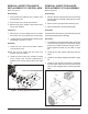
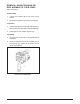
4. Remove the plug (66) from the filter cover (67).
5. Use a 7/8 inch wrench to remove the filter cover
assembly (67) from the auxiliary pump.
6. Remove the O-ring and filter (54).
7. Remove the charge relief valve assembly (44)
and auxiliary relief valve assembly (45) from the
auxiliary pump.
Inspection
1. With the auxiliary pump removed, inspect the
pump running surfaces for wear or damage.
2. Inspect all O-rings, gasket and mounting seats.
REMOVAL, INSPECTION AND/OR
REPLACEMENT OF AUXILIARY
PUMP (IF EQUIPPED)
3. Inspect the filter cover assembly threads and
filter for wear, damage or foreign material.
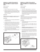
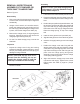
Assembly
1. Install the check ball, spring, and cap as one
assembly (45) into the auxiliary relief valve port.
Tighten to the correct torque value. See page
56.
2. Install the poppet, spring and cap (44) as one
assembly into the charge relief port. Tighten to
the correct torque value. See page 56.
3. Install the filter (54) and O-ring onto the filter
cover assembly (67). Install the assembly (67)
into the auxiliary pump and tighten. Install plug
(66) into the filter cover (67).
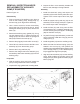
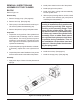
4. Lay the PJ Pump (input shaft down), so the end
cap is horizontal. Install the O-ring (8) into the
charge pump (7).
5. Install the gasket (75) onto the auxiliary pump.
6. Make sure that the ball and spring (44A) are
seated in the end cap (2), then position the
auxiliary pump and gasket with the aligning mark
on the charge pump (7). Insure that the pump
fully engages the alignment pins (69).
7. Align and insert the bolts (10) into the auxiliary
pump. While holding the auxiliary pump and
charge pump in place, tighten the bolts (10) per
table 2, page 56.
Figure 10. Auxiliary Pump
75
8
7
2
69
8
44A
45
64
6
66
67
54
44
10