
Operator's Manual


23
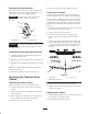
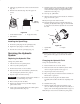
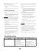
Checking the Paper Element
Inspect the element for tears, an oily film, damage to the
rubber seal, excessive dirt, or other damage (Fig. 21). If
any of these conditions exit, replace the filter.
Important Do not clean the paper element with
pressurized air or liquids, such as solvent, gas, or
kerosene.
m–3248
1
2
Figure 21
1. Paper element 2. Rubber seal
Important To prevent engine damage, always operate
the engine with the complete foam and paper air cleaner
assembly installed.
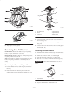
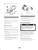
Installing the Foam and Paper Elements
1. Carefully slide the foam element onto the paper air
cleaner element (Fig. 19).
2. Slide the air cleaner assembly and cover onto the long
rod.
3. Install the cover nut finger-tight against the cover (Fig.
19).
Note: Ensure that the rubber seal is flat against the air
cleaner base and cover.
4. Install the air cleaner cover and knob (Fig. 19).
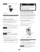
Servicing the Traction Drive
Chains
Lubricating the Drive Chains
Lubricate the drive chain every 50 operating hours.
1. Lower the loader arms, stop the engine, and remove
the key.
2. Apply a general purpose oil (10W30) onto upper and
lower chain spans.
3. Start the traction unit and slowly move it forward to
expose unlubed upper and lower chain spans.
4. Stop the engine and remove the key.
5. Apply oil to newly exposed unlubed chain spans.
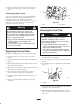
Checking the Tension
Check the drive chain tension before using the traction
unit for the first time and every 50 hours of use thereafter.
The drive chains should have about 1–1/2 to 2–1/2 inches
(3.8 to 6.35 cm) of slack between the bottom of the chain
guard and the bottom chain span when the top chain span
is pulled tight. Use the following procedure to check the
tension:
1. With the bucket installed, lower it into the ground until
the front tires are off of the ground.
2. Stop the engine and remove the key.
3. Turn the front wheel forward on one side of the
traction unit until the top span of the drive chain is
tight.
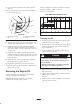
4. Measure the distance between the bottom of the chain
guard and the lower chain span (Fig. 22). If the slack
in the chain is not within 1–1/2 to 2–1/2 inches (3.8 to
6.35 cm), adjust the tension (refer to Adjusting the
Tension).
m–3962
1
2
3
Figure 22
1. Chain guard
2. Bottom span of the chain
3. 1–1/2” to 2–1/2”
5. Repeat steps 3 and 4 for the other drive chain.
6. Start the engine and raise the bucket to return the front
wheels to the ground.
Adjusting the Tension
1. With the bucket installed, lower it into the ground until
the front tires are off of the ground.
2. Stop the engine and remove the key.