
Service Manual

15
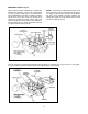
The pump consists of the following compo-
nents.
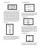
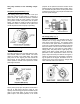
The piston group assembly. (Fig 4)
This rotating piston group is mounted to the input
shaft and is driven by the engine. It consists of a
piston block with numerous precision machined
bores which house the pump pistons. The small
pump pistons consist of the piston and the piston
slipper. The slipper is usually a brass or aluminum
component which is connected to the piston and
moves the pistons when the pump is operating.
Figure 4
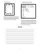
The swash plate. (Fig 5)
The piston slippers pivot and slide against a hard-
ened washer called a thrust washer. The thrust
washer is located in the swash plate. The swash
plate pivots on two support pins and controls the
pump output. As the operator moved the traction
control pedal to increase travel speed the swash
plate angle increases.
Figure 5
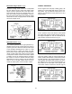
As the piston group spins the pistons are moved in
and out of their bores and they pump oil. The
quantity of the oil being pumped is controlled by the
angle of the swash plate. As long as the swash
plate is kept in the neutral position, no oil will be
pumped. As the operator moves the traction control
pedal the angle of the swash plate increases, this in
turn increases the piston travel. As the piston travel
increases the amount of oil pumped increases and
the travel speed changes.
Figure 6
The charge pump. (Fig 7)
While the transmission is in operation there is a
constant loss of oil (by design) within the compo-
nents of the pump and motor. For example, holes
in the end of each piston allow a small amount of
oil to form a cushion between the slipper’s face and
the thrust washer. This oil must be continuously re-
plenished. Built in to the system is pump called a
charge pump. This pump can be a gear pump, or a
gerotor pump. Both of these pumps are fixed dis-
placement. Fixed displacement means that the
pump’s output is fixed by the RPM of the engine. It
cannot be varied except by increasing or decreas-
ing the speed of the engine. Excessive oil not re-
quired by the drive circuit opens the charge relief
valve and flows back to the reservoir.
Figure 7