
Service Manual


Rev. 000
TX 413 Service Manual
7-13
HYDRAULIC LIFT ASSEMBLY
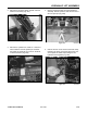
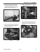
2. Remove the two hose clamps located under the
loader arm assembly (Fig. 227).
Figure 227 DSC-0968
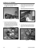
3. Remove the cylinder lock, install a 4 x 4 block of
wood under the front lift cylinder pin and lower
the loader arm assembly so it rests on the block
of wood and frame (Fig. 228).
Figure 228 DSC-0976
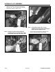
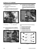
5. Remove the rear cover. Remove the hose clamp,
located in the back, on the lower left corner, and
cut the plastic tie cable strap holding the two
hydraulic hoses together (Fig. 230).
Figure 230 DSC-0969
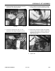
4. Place a jack stand under the quick attachment
assembly. Extend cylinder to ease the removal of
ram end pivot pin (Fig. 229).
Figure 229 DSC-0978