
Service Manual


Rev. 000
HYDRAULIC LIFT ASSEMBLY
7-14
TX 413 Service Manual
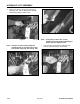
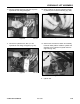
Figure 233 DSC-0973
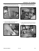
Note: It may help to remove the “Line D”
hydraulic valve fitting before attempting to
remove the next hydraulic hose.
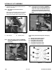
7. (Fig. 234, Ref. C) Remove the hydraulic hose
from the hydraulic fitting on the lift valve.
Figure 234 DSC-0971
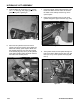
Figure 232 DSC-0972
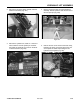
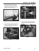
6. Place an oil drain pan under the control valve
hoses (Fig. 231, Ref. D). Remove the hydraulic
hose from the fitting on the lift valve.
Figure 231 DSC-0970
Note: Use paint or other marking method to
mark both ends of one hose and its valve
and cylinder fitting (Fig. 232 and Fig. 233).