
Service Manual


Rev. 000
TX 413 Service Manual
7-15
HYDRAULIC LIFT ASSEMBLY
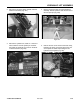
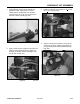
8. Pull the two hydraulic hoses from the rear of the
unit out the side, under the loader arm (Fig. 235).
Figure 235 DSC-0975
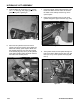
9. Pull the two hydraulic hoses through the front
opening of the loader arm (Fig. 236).
Figure 236 DSC-0977
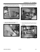
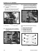
11. Using a drift punch and a hammer, drive the pivot
pin out of the ram end of the hydraulic tilt cylinder
(Fig. 238).
Figure 238 DSC-0980
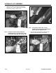
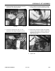
Figure 237 DSC-0979
10. Remove the shoulder bolt that holds the pivot
pin on the ram end of the hydraulic cylinder (Fig.
237).