
Service Manual


Rev. 000
TX 413 Service Manual
7-17
HYDRAULIC LIFT ASSEMBLY
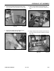
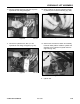
3. Install the bolt and nut and torque to 16 + 2 ft-lbs.
(21.7 + 2.7 Nm) (Fig. 244).
Figure 244 DSC-0988
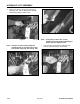
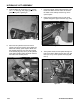
2. Apply a small amount of grease to the end of the
pivot pin on the barrel end of the cylinder and
slide the pin through until the holes align up for
the bolt and nut (Fig. 243).
Figure 243 DSC-0987
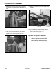
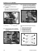
4. Apply a small amount of grease to the pivot pin
on the ram end of the cylinder and slide the pin
through and align the locking shoulder bolt hole
(Fig. 245).
Figure 245 DSC-0989
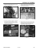
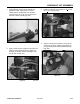
Figure 242 DSC-1017A
1. Install hydraulic hoses to the tilt cylinder and
tighten the hoses, making sure to connect
marked hose to marked fitting. For reference
purposes, hose “D” in Fig. 231 connects to the
ram end of the tilt cylinder (Fig. 242).