
Service Manual


Rev. 000
HYDRAULIC LIFT ASSEMBLY
7-20
TX 413 Service Manual
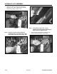
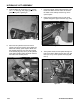
Note: Units with a serial number of 240000100
through 240000200 have the clamp shown
in Fig. 255.
Figure 255 DSC-1072
Figure 256 DSC-1073
Note: Units with a serial number of 240000201
and higher have a revised hydraulic hose
clamp. It is easier to install this clamp by
using a crescent wrench to pry down on
the bracket to install the bolt and nut (Fig.
256).
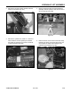
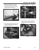
14. Install the two hose clamps located under the
loader arm assembly.
Note: The clamps have wide and narrow
channels.
Make sure the wide channel goes to the outside
of the loader arm, retaining the two hydraulic
hoses for the auxiliary quick couplers (Fig. 254).
Figure 254 DSC-0968
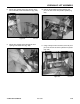
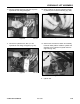
B
A
Proper hose placement through the clamp (Fig.
257).
A. Auxiliary Hose (female coupler)
B. Auxiliary Hose (male coupler)
C. Lift Cylinder Hose (ram end)
D. Tilt Cylinder Hose (ram end)
E. Tilt Cylinder Hose (barrel end)
F. Lift Cylinder Hose (barrel end)
Figure 257 105-9000 clamp
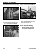
Front
Rear
A
B
C
D
E
F
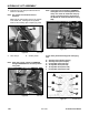
A. Hose clamps B. Auxiliary hoses