
Service Manual


Rev. 000
TX 413 Service Manual
7-21
HYDRAULIC LIFT ASSEMBLY
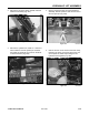
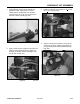
15. Install cable tie strap around all four hydraulic
hoses, approximately 8" (20.32cm) to the right of
the rear clamp (Fig. 258).
17. Start the unit and remove the cylinder lock
assembly. Operate the loader valve up, down,
and tilt to purge the system of any air. Check for
any oil leaks at the hydraulic hose connectors.
After running the hydraulics recheck the oil
reservoir; see the Maintenance Section, Checking
the Hydraulic Reservoir, page 3-4. Shut engine
off.
18. Install the rear cover.
Figure 258 DSC-1075
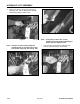
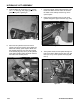
16. Install a cable tie around all four hydraulic hoses,
about 3” (7.62cm) from the back hose clamp in
the Loader Arm Assembly (Fig. 259).
Figure 259 DSC-1071
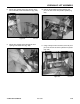
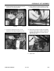
Hydraulic Lift Cylinder Removal
Note: Units with serial numbers from 240000100
through 240000200 have a fixed fitting at
the mounting end of the lift cylinder. You
will need to hold the hydraulic line with
a wrench and turn the cylinder until the
hydraulic line is disconnected from the
cylinder (Fig. 260).
Figure 260 DSC-1031
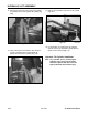
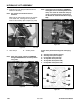
Figure 261 DSC-1032
Note: Units with serial numbers from 240000201
and higher have a swivel fitting at the ram
end of cylinder (Fig. 261).