
Service Manual


Rev. 000
HYDRAULIC LIFT ASSEMBLY
7-22
TX 413 Service Manual
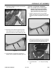
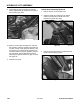
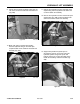
Figure 264 DSC-1026
3. Place an oil drain pan under the control valve.
Mark the hydraulic hose and fitting with a marker
or paint (Fig. 264).
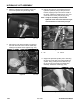
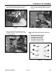
2. Start the unit and raise the loader arm. Place a
jack stand under the quick attachment assembly
and lower the loader arm so it is supported by the
jack stand. The pivot pin on the ram end of the
hydraulic lift cylinder should be approximately 10"
(25.4cm) from the frame (Fig. 263).
Figure 263 DSC-0998
Note: Cleanliness is a key factor in a successful
repair of any hydraulic cylinder.
Thoroughly clean all exposed surfaces
prior to any type of maintenance. Cleaning
all parts by using a solvent wash and air
drying is usually adequate. As with any
precision equipment, all parts must be kept
free of foreign material and chemicals.
Protect all exposed sealing areas and open
cavities from damage and foreign material.
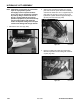
1. Remove the rear cover (Fig. 262).
Figure 262 DSC-0778