
Service Manual


Rev. 000
TX 413 Service Manual
7-23
HYDRAULIC LIFT ASSEMBLY
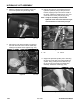
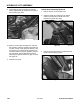
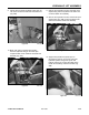
6. Remove the bolt and nut on the pivot pin located
at the barrel end of the hydraulic cylinder (Fig.
267).
Figure 267 DSC-0997
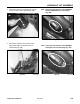
7. Remove the hydraulic hose from the fitting on the
hydraulic lift valve (Fig. 268).
Figure 268 DSC-1024
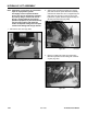
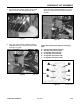
5. Remove the bolt and nut on the pivot pin located
at the ram end of the hydraulic lift cylinder (Fig.
266).
Figure 266 DSC-0996
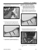
Figure 265 DSC-1025
4. Remove the hydraulic hose from the fitting on the
hydraulic lift valve (Fig. 265).