
Service Manual


Rev. 000
TX 413 Service Manual
7-25
HYDRAULIC LIFT ASSEMBLY
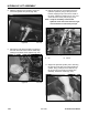
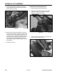
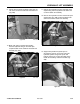
2. Route the two hydraulic hoses from the hydraulic
lift cylinder through the frame opening to the rear
of the barrel end of the lift cylinder (Fig. 276).
Figure 274 DSC-1018
Figure 276 DSC-1020
Hydraulic Lift Cylinder Installation
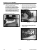
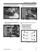
13. Remove the three cable ties (Note the location
of the cable ties) from the hydraulic hoses and
remove the hoses from the lift cylinder (Fig. 274).
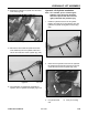
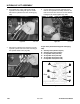
Note: As a reminder, prior to connecting the
hydraulic lines, the O-rings and seals
should be replaced with new ones and
lightly lubricated with petroleum jelly.
1. Install the hydraulic hoses to the lift cylinder.
Replace the cable ties to the hydraulic hose and
hydraulic lift cylinder and tighten the hoses (Fig.
275).
Figure 275 DSC-1018
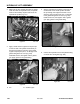
14. For information on repairing the Hydraulic Lift
Cylinder, refer to Hydraulic Lift Repair, page 7-40.
12. Remove the hydraulic lift cylinder from the frame
of the unit (Fig. 273).
Figure 273 DSC-1016
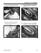
A
A. Lift cylinder barrel B. Pivot pin mounting
end
B