
Service Manual


Rev. 000
HYDRAULIC LIFT ASSEMBLY
7-26
TX 413 Service Manual
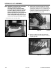
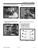
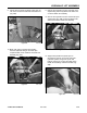
6. Connect the hydraulic hose to the hydraulic fitting
on the lift valve and tighten (Fig. 280).
Figure 280 DSC-1024
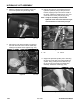
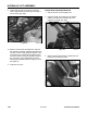
5. Apply a small amount of grease to the pivot pin
on the barrel end of the lift cylinder and slide
the pin through, then align the bolt hole. Use a
socket or pipe to tap the pivot pin in, so damage
to the grease fitting does not occur (Fig. 279).
Install bolt and nut, then tighten. With a grease
gun, apply grease to the grease fitting.
Figure 279 DSC-1023
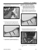
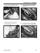
4. Apply a small amount of grease to the pivot pin
on the ram end of lift cylinder and slide the pin
through, then align the bolt hole. Use a socket
or pipe to tap the pivot pin in, so damage to the
grease fitting does not occur (Fig. 278).
Install bolt and nut, then tighten. With a grease
gun, apply grease to the grease fitting.
Figure 278 DSC-1022
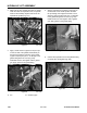
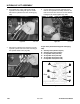
3. Make sure the two hydraulic lift hoses are routed
under the other four hydraulic hoses; 2 hydraulic
hoses for the auxiliary couplers and two for the
hydraulic tilt cylinder (Fig. 277).
Figure 277 DSC-1028
B
A
A. Pin B. Socket or pipe