
Service Manual


Rev. 000
TX 413 Service Manual
7-31
HYDRAULIC LIFT ASSEMBLY
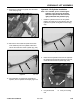
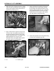
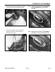
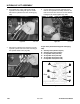
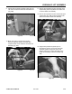
13. Support the hydraulic lift cylinder prior to
removing the pivot pin on the ram end of the
hydraulic cylinder. Using a drift punch and
hammer, tap the pin out from the inside of the
loader arm assembly, toward the outside (Fig.
299).
Figure 299 DSC-1015
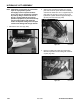
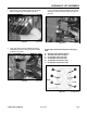
10. Mark, (with paint or marker) the hydraulic
hose and hydraulic fitting on the male quick
coupler located on the outside of the loader arm
assembly (Fig. 297).
Figure 297 DSC-1053
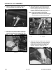
Figure 298 DSC-1054
11. Remove the hydraulic hose from the male quick
coupler fitting. Pull the hydraulic hose down and
out of the loader arm assembly.
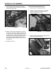
12. Remove the hydraulic hose from the female quick
coupler fitting (Fig. 298). Pull the hydraulic hose
down and out of the loader arm assembly.
9. Pull the two tilt cylinder hydraulic hoses from the
rear of the unit out the side under the loader arm
(Fig. 296).
Figure 296 DSC-0975