
Service Manual


Rev. 000
HYDRAULIC LIFT ASSEMBLY
7-34
TX 413 Service Manual
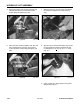
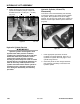
8. Align the hole for the bolt that retains the pivot pin
for the hydraulic lift cylinder. Install the bolt and
nut and tighten to 16 + 2 ft-lbs. (21.7 + 2.7 Nm)
(Fig. 311).
Figure 311 DSC-1043
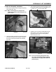
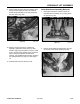
7. Grease the pivot pin for ram end of the hydraulic
lift cylinder and install on the loader arm (Fig.
310).
Figure 310 DSC-1066
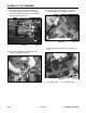
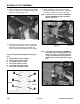
5. Route the auxiliary hose through the loader arm
assembly and connect it to the female quick
coupler fitting and tighten (Fig. 308).
Figure 308 DSC-1054
6. Route the other auxiliary hydraulic hose, (the one
that is marked when removed), and connect it
to the male quick coupler fitting and tighten (Fig.
309).
Figure 309 DSC-1053
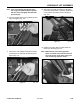
9. Using a grease gun, apply grease to the grease
fitting for the pivot pin.