
Service Manual


Rev. 000
HYDRAULIC LIFT ASSEMBLY
7-38
TX 413 Service Manual
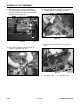
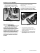
6. Slide the quick attachment assembly away from
the loader arms (Fig. 326).
Figure 326 DSC-1083
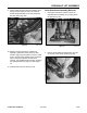
5. Remove the right and left shoulder bolt retaining
the pivot pins located on both sides of the quick
attachment assembly. Remove both pivot pins
(Fig. 325).
Figure 325 DSC-1081
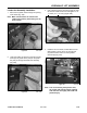
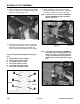
4. Support the tilt cylinder and remove the pivot pin
(Fig. 324).
Figure 324 DSC-1080
3. Tap the pivot pin out of the ram end of the tilt
cylinder using a hammer and drift punch (Fig.
323).
Figure 323 DSC-1079