
Service Manual


Rev. 000
HYDRAULIC LIFT ASSEMBLY
7-40
TX 413 Service Manual
Hydraulic Cylinder Service
Hydraulic cylinders are designed to hold
hydraulic fluid under pressure. In addition,
cylinders may contain holding valves and other
means that could cause pressure to remain
locked in the cylinder. As such, incorrect
handling or process steps can create an unsafe
situation. Be sure all appropriate measures are
taken to relieve any residual pressure in the
cylinder and further ensure that the cylinder is
restrained in such a way that it cannot fall or
move during the disassembly and assembly
processes.
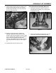
Figure 332 DSC-1375
Hydraulic Cylinder, Lift and Tilt,
Disassembly
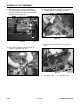
This section covers the disassembly and assembly
on both the Hydraulic Lift Cylinder and the Hydraulic
Tilt Cylinder. Both cylinders are similar in design;
however, the removal of the heads of the cylinder are
different and will require different spanner wrenches
(Fig. 332).
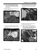
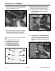
4. Grease the pivot pin for the ram end of the
cylinder and install the pivot pin. Torque the
shoulder bolt to 16 + 2 ft-lbs. (21.7 + 2.7 Nm)
(Fig. 331).
Figure 331 DSC-1080
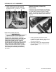
WARNING!
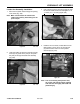
1. Follow appropriate procedures for either
Hydraulic Lift Cylinder Removal, page 7-21; or
Hydraulic Tilt Cylinder Removal, page 7-12 for
cylinder being serviced.
2. Clean away all dirt or other foreign substance
from openings, particularly at the head of the
hydraulic cylinder.