
Service Manual


Rev. 000
TX 413 Service Manual
7-41
HYDRAULIC LIFT ASSEMBLY
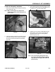
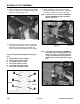
3. Using a spanner wrench, install in the holes
provided. Rotate the head clockwise until
the edge of the retaining ring appears in the
milled opening of the tube. Insert a flat blade
screwdriver between the beveled edge of the
retaining ring and the cylinder barrel to start the
retaining ring through the opening.
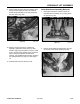
5. Pull out on the rod to remove the piston and head
assembly from barrel (Fig. 335).
Figure 335 DSC-1338
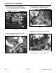
4. Rotate counter-clockwise until the retaining ring is
completely removed (Fig. 334).
Figure 334 DSC-1335
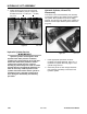
Note: If excessive wear due to side-loads or
binding is a possibility, mark or note the
piston and head relationship to the rod
and tube. This condition will usually show
up as a highly polished surface on the
piston and head 90° to the pin rotation axis
(Fig. 333).
Figure 333 DSC-1329