
Service Manual


Rev. 000
TX 413 Service Manual
7-45
HYDRAULIC LIFT ASSEMBLY
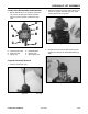
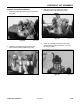
12. Lubricate the ID of the piston and install on the
rod (Fig. 347).
Figure 347 DSC-1363
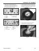
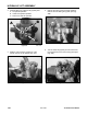
10. Install tape around the threads on the rod and
install the PRS Static O-ring onto the rod and
remove tape (Fig. 345).
Figure 345 DSC-1361
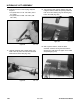
11. Lubricate the ID of the head and install on the rod
(Fig. 346).
Figure 346 DSC-1362
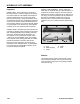
9. Spread the Wear Ring into a "C" shape only
enough to fit over the outside of the piston and
snap it into its groove (Fig. 344).
Figure 344 DSC-1360