
Service Manual


Rev. 000
HYDRAULIC LIFT ASSEMBLY
7-46
TX 413 Service Manual
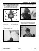
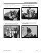
16. With a spanner wrench, rotate the head
clockwise. Continue turning the head until the
retaining ring edge does not appear in the milled
slot opening (Fig. 351).
Figure 351 DSC-1374
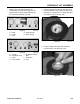
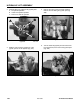
14. Lubricate inside the tube, outside piston, and
head. Insert the piston into tube until the head
meets the end of the tube (Fig. 349).
Figure 349 DSC-1367
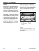
13. Install the lock nut on the rod (Fig. 348) and
torque to:
tilt cylinder lock nut 175 - 200 ft-lbs. (237.3 -
271.2 Nm)
lift cylinder lock nut 250 - 300 ft lbs. (339 -
406.7 Nm)
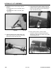
15. Turn head into tube until the retaining ring hole
is aligned with the milled slot opening. Install the
hook end of the retaining ring into retaining ring
hole in the head (Fig. 350).
Figure 348 DSC-1364
Figure 350 DSC-1373