
Service Manual


Rev. 000
TX 413 Service Manual
7-51
HYDRAULIC LIFT ASSEMBLY
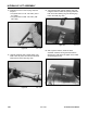
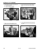
4. Turn the loader lift joystick joint and remove the
nut retaining it to the lift spool (Fig. 370).
Figure 370 DSC-1397
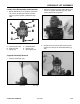
5. Remove the two hex head retaining screws that
retain the joystick pivot (Fig. 371).
Figure 371 DSC-1398
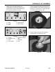
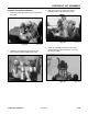
3. Slide the rod end off the joystick pin and remove
the pin (Fig. 369).
Figure 369 DSC-1726
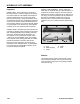
2. Remove the 3 hex head screws and spring lock
washers and remove the articulated holder (Fig.
368).
Figure 368 DSC-1382