
Service Manual


Rev. 000
HYDRAULIC LIFT ASSEMBLY
7-52
TX 413 Service Manual
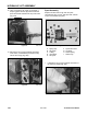
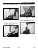
8. Using a drift punch to hold the top end of the
spool, remove the detent spring assembly from
the bottom of the spool (Fig. 374).
Figure 374 DSC-1404
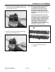
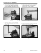
7. Turn the valve assembly over. Remove the two
hex head retaining screws securing each spring
cap and remove (Fig. 373).
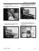
9. Using a drift punch to hold the top end of the
spool, remove the spring valve assembly with a
hex wrench (Fig. 375).
Figure 373 DSC-1400
Figure 375 DSC-1406
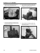
6. Remove two hex head retaining screws that
retain the joystick base plate (Fig. 372).
Figure 372 DSC-1399