
Service Manual


Rev. 000
TX 413 Service Manual
7-61
HYDRAULIC LIFT ASSEMBLY
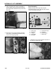
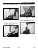
6. Remove the two o-rings located at each end of
the valve. A small dental pick works to remove
the o-ring (Fig. 409).
Figure 409 DSC-1451
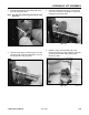
7. Remove relief plug cavity (Fig. 410).
Figure 410 DSC-1452
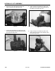
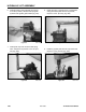
4. Remove the bottom neutral switch block by
removing the two hex cap screws (Fig. 407).
Figure 407 DSC-1448
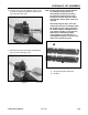
5. Remove the spool from the bottom of valve (Fig.
408).
Figure 408 DSC-1450
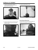
Note: Visually inspect spool outside surfaces
for scratches. Deep scratches are
unacceptable and the spool needs to be
replaced. Scratches deep enough to catch
the fingernail are also unacceptable and
the spool needs to be replaced. Before
replacing the spool, clean and inspect the
inner bore for damage. Check the condition
of the o-rings particularly for metallic
particles embedded in the o-ring surface.
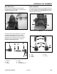
Damage to o-ring grooves, particularly on
the sealing surface, is unacceptable. In
the event that an unacceptable condition
occurs, the valve needs to be replaced.