
Service Manual


Rev. 000
TX 413 Service Manual
8-3
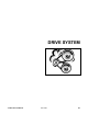
DRIVE SYSTEM
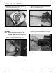
Figure 422 DSC-0788
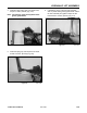
Figure 424 DSC-0783
Figure 423 DSC-0782
Figure 425 DSC-0790
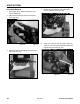
6. Pry down with the pry bar to remove tension and
remove the belt from the engine drive pulley (Fig.
422).
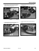
Drive Belt Installation
1. Start by taking the belt and feeding it through the
rear of the unit, around the gear pump pulley and
then around both the lower and upper hydraulic
pump pulleys (Fig. 424).
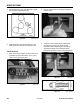
7. Remove the belt around the upper and lower
hydraulic pump pulleys, and around the gear
pump pulley. Slide the belt out the rear of the unit
(Fig. 423).
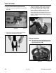
2. Using a 12" (30.5cm) crow foot pry bar, insert
the crow foot end of the pry bar between the
idler pivot shaft and the pivot arm tab. Pry down
(clockwise) on the pry bar and install the belt
around the engine drive pulley (Fig. 425).