
Service Manual


Rev. 000
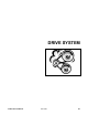
DRIVE SYSTEM
Figure 435 DSC-1724
8-6
TX 413 Service Manual
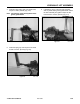
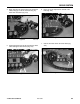
Note: The raised inner race of the bearing should
be facing outward on both bearings on the
tensioner wheel (Fig. 438).
Figure 438 DSC-0810
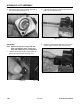
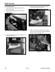
Tensioner Wheel Bearing Replacement
1. Remove tensioner arm assembly out of the frame
(Fig. 435).
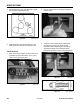
3. Support the tensioner wheel so there is a space
under it for bearing removal. Using a hammer,
drive the upper bearing down to create a gap
between spacer and bearing, then use a drift
punch to hammer the lower bearing out. The
spacer will fall out when bearing is removed. Turn
the tensioner wheel over and drive out the other
bearing. Inspect the tensioner wheel housing and
spacer (Fig. 437).
2. Remove the bolt and nut holding the tensioner
wheel to the tensioner arm (Fig. 436).
Bearing Installation
Figure 436 DSC-0804
Figure 437 DSC-0808