
Service Manual


TX 413 Service Manual
8-9
DRIVE SYSTEM
Rev. 000
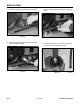
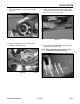
Figure 449 DSC-0801
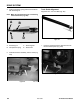
Track Installation
1. Engage the lugs on the track between the
spacers on the drive sprocket (Fig. 449).
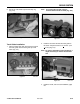
Figure 447 DSC-0629
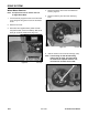
Figure 448 DSC-0631
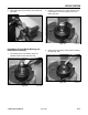
Figure 446 DSC-0628
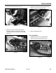
2. Secure the end with the pin (Fig. 446).
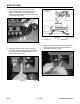
3. Rotate the tool and move the track guide as
necessary until the tool fi ts into the track guide
channel. Secure the end of the tool with a strap
(Fig. 447).
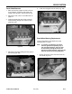
4. Tighten and torque the 4 track guide mounting
bolts to 75 ft lbs (102 Nm) (Fig. 448).
5. Remove the alignment tool.