
Service Manual


Rev. 000
TX 413 Service Manual
8-15
DRIVE SYSTEM
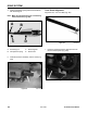
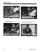
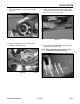
Figure 470 DSC-0821
8. Secure the road wheel cap with the snap ring
(Fig. 470).
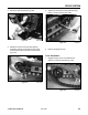
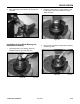
Figure 471 DSC-0817
Track Guide Installation
1. With a hydraulic floor jack and a board to support
the track guide, raise the track guide up to the
frame (Fig. 471).
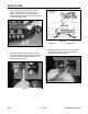
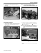
Note: The track guide end with a step is
mounted toward the drive wheel (Fig. 472).
Figure 472 DSC-0619
3. Install the tracks; refer to Track Installation, page
8-8.
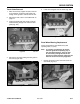
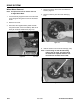
2. Install the four bolts that hold the track guide to
the frame. Torque the bolts to 75 + 8 ft-lbs. (102
+ 11 Nm) (Fig. 473).
Note: For ease of installation of the inside bolt, it
maybe necessary to remove the tensioner
arm.
Figure 473 DSC-1725