
Service Manual


Rev. 000
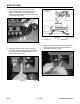
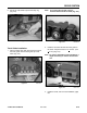
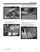
6. Remove castle nut on the motor shaft (Fig. 476).
Note: A self-locking nut with thread-locking
material may be used. This self-locking
nut needs to be replaced whenever it is
removed from the wheel motor shaft.
Figure 476 DSC-0838
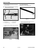
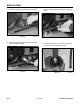
Figure 474 DSC-0856
DRIVE SYSTEM
Wheel Motor Removal
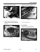
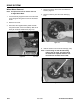
4. Remove the track; refer to the Track Removal
section, page 8-4.
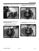
5. Remove cotter key from the motor shaft (Fig.
475).
Figure 475 DSC-0837
8-16
TX 413 Service Manual
Note: This procedure can be used for the Left
or Right Wheel Motor
1. Lift and securely support the unit so that the track
is far enough off the ground to remove the wheel
motor.
2. Remove rear cover.
3. Disconnect the negative battery cable and then
the positive cable; remove the battery. Slide an oil
drain pan under the wheel motor (Fig. 474).