
Service Manual


Rev. 000
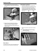
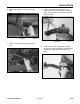
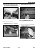
3. Mark or tag the right side linkage rod and remove
the bolt, spacer, and nut in the rod end bearing
(Fig. 490).
Figure 490 DSC-1264
DRIVE SYSTEM
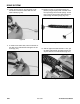
7. Install track; refer the Track Installation, page 8-8.
8. Reinstall battery and battery cables; connect
positive cable first.
9. Purge the unit of any air that may be trapped
in the hydraulic system; refer to Purging Air
Procedures, page 6-4. Check for any oil leaks.
10. Lower the unit to the ground and reinstall the rear
cover and belt cover.
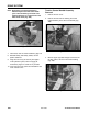
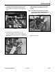
Note: Self-locking nut with thread-locking
material may be used with some model
years. This self-locking nut needs to be
replaced whenever it is removed from the
wheel motor shaft (Fig. 488).
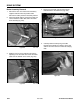
Traction Control Handle Assembly
Removal
1. Remove the rear cover.
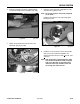
2. Remove the bolt and nut retaining the control
handle assembly to the drive rod assembly (Fig.
489).
Figure 488 DSC-0852
Figure 489 DSC-1247
8-20
TX 413 Service Manual